EasyManua.ls Logo

Keithley 617 User Manual

Keithley 617
183 pages
To Next Page IconTo Next Page
To Previous Page IconTo Previous Page
Page #87 background imageLoading...
Page #87 background image
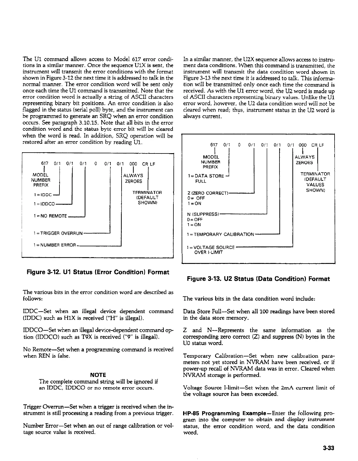
The Ul command allows access to Model 617 error condi-
tions in a similar manner. Once the sequence UlX is sent, the
instrument will transmit the error conditions with the format
shown in Figure 3-12 the next time it is addressed to talk in the
normal manner. The error condition word will be sent only
once each time the Ul command is transmitted. Note that the
error condition word is actually a string of ASCII characters
representing binary bit positions. An error condition is also
flagged in the status (serial poll) byte, and the instrument can
be programmed to generate an SRQ when a” error condition
OCCWS. See paragraph 3.10.15. Note that all bits in the error
condition word and the status byte error bit will be cleared
when the word is read. In addition, SRQ operation will be
restored after an error condition by reading Ul.
r
617 Oil O/l 0,
I= IDDCO-
1= NO REMOTE -
0 0
1 1 = NUMBER ERROR
000 CR LF
,LWAYS
ZEROES
TERMINATOR
(DEFAULT
SHOWN1
1
Figure 3-12. Ul Status (Error Condition) Format
The various bits in the error condition word are described as
follows:
IDDC-Set when a” illegal device dependent command
(IDDC) such as HlX is received (“H” is illegal).
IDDCO-Set when a” illegal device-dependent command op-
tion (IDDCO) such as T9X is received (“9” is illegal).
No Remote-Set when a programming command is received
when REN is false.
NOTE
The complete command string will be ignored if
an IDDC. IDDCO or no remote error occurs.
Trigger Overrun-Set when a trigger is received when the in-
strument is still processing a reading from a previous trigger.
Number Error-Set when a” Out of range calibration or vol-
tage source value is received.
In a similar manner, the U2X sequence allows access to instru-
ment data conditions. When this command is transmitted, the
instrument will transmit the data condition word shown in
Figure 3-13 the next time it is addressed to talk. This informa-
tion will be transmitted only once each time the command is
received. As with the Ul error word, the U2 word is made up
of ASCII characters representing binary values. Unlike the Ul
error word, however, the LIZ data condition word will not be
cleared when read; thps, instrument status in the U2 word is
always current.
617 Oil 0 Oil o/1 0.
MODEL
NUMBER
PREFIX
1 = DATA STORE J
FULL
2 (ZERO CORRECT)
0= OFF
l=ON
N (SUPPRESS1
O=OFF
l=ON
1 =TEMPORARY CALlSRATlON-
0,
iI
1 =“OLTAGE SOURCE
OVER I-LIMIT
A
000 CR LF
I
.LWAYS
!EROES
TERMINATOR
,DEFAULT
VALUES
1
Figure 3-13. U2 Status (Data Condition) Format
The various bits in the data condition word include:
Data Store Full-Set when all 100 readings have been stored
in the data store memory.
Z and N-Represents the same information as the
corresponding zero correct (Z) and suppress (N) bytes in the
UO status word.
Temporary Calibration-Set when new calibration para-
meters not yet stored in NVRAM have been received, or if
power-up recall of NVRAM data was in error. Cleared when
NVRAM storage is performed.
Voltage Source I-limit-Set when the 2mA current limit of
the voltage source has been exceeded.
HP-85 Programming Example-Enter the following pro-
gram into the computer to obtain and display instrument
status, the error condition word, and the data condition
word.
3-33

Table of Contents

Other manuals for Keithley 617

Question and Answer IconNeed help?

Do you have a question about the Keithley 617 and is the answer not in the manual?

Keithley 617 Specifications

General IconGeneral
BrandKeithley
Model617
CategoryMeasuring Instruments
LanguageEnglish

Summary

Warranty Information

Warranty

Details the warranty terms and conditions for the product and specific components.

Specifications

Specifications

Details the electrical and performance specifications for the Model 617 electrometer.

Safety Precautions

Safety Precautions

Advises on essential safety measures to avoid injury and instrument damage during operation.

Section 1: General Information (Continued)

Unpacking and Getting Started

Details unpacking, inspection, and initial steps to operate the Model 617.

Section 2: Operation

2.2 Power Up Procedure

Details the steps for connecting power and turning on the instrument.

2.3 Power Up Self Test and Display Messages

Explains the self-test routine and potential display messages upon startup.

Section 2: Operation (Continued)

2.4 Front Panel Familiarization

Provides an overview of the Model 617's front panel layout, controls, and indicators.

2.7 Basic Measurement Techniques

Introduces fundamental procedures for making voltage, resistance, charge, and current measurements.

2.7.2 Input Connections

Details how to connect input signals to the rear panel INPUT connector.

2.7.4 Guarded Operation

Explains the concept and application of guarding to minimize leakage and improve measurements.

2.7.5 Making Current Measurements

Details the procedure for measuring low-level currents, including picoampere ranges.

2.7.6 Making Charge Measurements

Describes how to measure charge using the Model 617's coulombs ranges.

2.7.7 Resistance Measurements

Explains how to measure resistance using constant current and voltage methods.

2.8 Using The Voltage Source

Explains how to use the Model 617's built-in voltage source for V/I measurements.

2.10 Using External Feedback

Explains how to extend capabilities using external feedback networks.

2.11 Using Zero Correct and Baseline Suppression

Covers instrument offset cancellation and baseline value storage.

2.11.2 Using Suppression

Details how to store an offset value and subtract it from subsequent readings.

2.13 External Triggering

Explains how to trigger the instrument using external BNC connectors.

2.4.1 Controls

Describes the function and operation of each front panel control button.

2.5.3 Calibration

Introduces the digital calibration program for front panel or IEEE-488 bus use.

2.7.3 Making Voltage Measurements

Provides step-by-step instructions for measuring DC voltages with the Model 617.

2.8.1 Basic Operating Procedure

Guides on connecting and adjusting the voltage source output.

2.11.1 Zero Correct and Zero Check

Explains how to use Zero Correct and Zero Check to cancel internal offsets.

2.12 Data Storage

Describes the internal 100-point data store mode for logging readings.

2.13.1 External Trigger

Details continuous and one-shot triggering modes via the external trigger input.

2.14 Measurement Considerations

Discusses factors affecting measurements at low signal levels.

2.8.2 V/I Resistance Measurements

Describes how to measure high resistances using the voltage source and electrometer.

Section 3: IEEE-488 Programming

Section 3: IEEE-488 Programming (Continued)

3.4 Bus Commands

Covers device commands, grouped into uniline, multiline, and device-dependent categories.

3.7.2 Bus Connections

Details how to connect the Model 617 to the IEEE-488 bus using appropriate cables.

3.7.3 Primary Address Programming

Explains how to check and set the instrument's primary address for bus communication.

3.8 Software Considerations

Discusses software aspects for IEEE-488 controllers like HP-85 and IBM-PC.

3.9 General Bus Command Programming

Covers general bus commands like DCL, REN, IFC, LLO, GTL, SDC, GET, SPE, SPD.

3.10 Device-Dependent Command Programming

Details commands controlling modes like function, range, trigger, and data format.

3.10.2 Function (F)

Describes commands to select measurement functions like Volts, Amps, Ohms, Coulombs.

3.10.3 Range (R)

Explains commands for controlling instrument sensitivity and selecting measurement ranges.

3.10.4 Zero Correct and Zero Check (Z and C)

Details commands for canceling internal offsets and zeroing the instrument.

3.10.5 Baseline Suppression (N)

Explains commands to store an offset and subtract it from subsequent readings.

3.10.9 Voltage Source Value (V)

Details commands for programming the built-in voltage source output.

3.4.5 Device-Dependent Commands

Describes commands specific to device configuration, controlling functions like mode and range.

3.10.8 Data Store Mode

Explains how to use the data store for logging readings and setting intervals.

3.10.11 Calibration Value (A)

Describes commands for setting calibration values for ranges and functions.

Section 4: Applications

4.2 Insulation Resistance Measurements

Details how to measure high insulation resistances using constant current and voltage methods.

Section 4: Applications (Continued)

4.3 High Impedance Voltmeter

Explains using the Model 617 as a high-impedance voltmeter with minimal circuit loading.

4.4 Low-Level Leakage Current Measurements

Guides on measuring low-level currents like nanoamperes and picoamperes.

Section 5: Performance Verification

Section 5: Performance Verification (Continued)

5.5 Verification Procedures

Provides detailed procedures for verifying accuracy of volts, ohms, amps, and coulombs functions.

Section 7: Maintenance

Section 7: Maintenance (Continued)

7.4.5 Front Panel Calibration

Provides step-by-step instructions for calibrating from the front panel.

7.4.11 Amps Calibration

Provides calibration steps for the amps function across various ranges.

7.4.12 Coulombs Calibration

Details the procedure for calibrating the coulombs function.

7.4.14 Ohms Calibration

Provides calibration steps for the ohms function across various ranges.

7.4.15 Voltage Source Calibration

Details the procedure for calibrating the instrument's internal voltage source.

7.4 Calibration

Introduces digital calibration capabilities and recommendations.

7.4.6 IEEE-488 Bus Calibration

Details procedures for calibrating the instrument via the IEEE-488 bus using a computer.

7.4.8 Input Offset Adjustment

Describes steps to null any small offset in the input amplifier.

7.4.13 Volts Calibration

Outlines the calibration steps for the volts function across different ranges.

7.7 Troubleshooting

Offers guidance for diagnosing and resolving instrument problems.

7.4.9 Input Current Adjustment

Details procedures to null input current in the input stage for temperature compensation.

Related product manuals