11-12 Limit Testing
Category register component handler
When using this type of handler, the SourceMeter sends a bit pattern to three handler lines
when a pass or fail condition occurs. This bit pattern determines the bin assignment for the
DUT. With the pass/fail pattern on the output, line #4 is then pulsed. This EOT (end-of-test)
pulse latches the bit pattern into the register of the handler, which places the DUT in the
assigned bin. When interfacing to this type of handler, a maximum of eight component handler
bins are supported.
If the handler requires a high-going or low-going EOT pulse, program SourceMeter for 3-bit
operation and appropriate EOT mode.
NOTE The EOT and 3-bit modes are configured from the CONFIG LIMIT MENU. See
“Configuring limit tests” later in this section.
Basic binning systems
Two basic binning systems are shown in Figures 11-7 and 11-8. Both systems require a han-
dler to physically place the device packages in the appropriate bins. The handler is controlled
by the SourceMeter via the Digital I/O port.
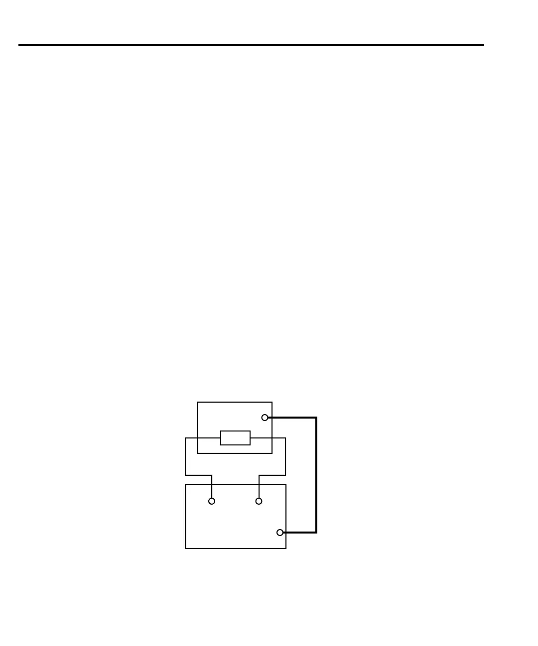
Single-element device binning
Figure 11-7 shows a basic binning system for single-element devices (i.e., resistors). After
all programmed testing on the DUT is completed, the appropriate digital output information is
sent to the component handler, which then places the DUT in the appropriate bin. The compo-
nent handler selects the next DUT, and the testing process is repeated.
Handler
Dig
In
DUT
HI
LO
IN/OUT
6430
Dig
I/O
igure 11-7
inning system - single
element devices