Source-Measure Concepts 5-23
Inside the test fixture, a triaxial cable can be used to extend guard to the DUT. The center
conductor of the cable is used for In/Out HI, the inner shield is used for guard, and the outer
shield is used for In/Out LO and is connected to the safety shield (which is connected to safety
earth ground).
A coaxial cable can be used if the guard potential does not exceed 30Vrms (42.4V peak).
The center conductor is used for In/Out HI, and the outer shield is used for guard. For higher
guard potentials, use a triaxial cable as previously explained.
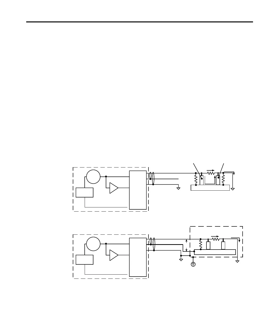
Figure 5-12 shows how cable guard can eliminate leakage current through the insulators in a
test fixture. In Figure 5-12A, leakage current (I
L
) flows through the insulators (R
L1
and R
L2
) to
In/Out LO, adversely affecting the low-current (or high-resistance) measurement of the DUT.
In Figure 5-12B, the driven guard is connected to the metal guard plate for the insulators.
Since the voltage on either end of R
L1
is the same (0V drop), no current can flow through the
leakage resistance path. Thus, the SourceMeter only measures the current through the DUT.
Cable guard should be used when sourcing or measuring low current (<1µA).
NOTE When using shielded, triaxial, or coaxial cabling with guard, cable guard (not ohms
guard) must be used to prevent oscillations. CABLE guard is the factory default
setting.
6430
I-Meter
x1
REMOTE
PreAmp
In/Out HI
In/Out LO
V-Source
Guard
6430
I-Meter
x1
REMOTE
PreAmp
In/Out HI
In/Out LO
V-Source
Guard
HI (In/Out)
Guard (Cable)
Guard (Cable)
LO (In/Out)
LO (In/Out)
I
D
I
L
R
L2
I
M
I
D
I
L
DUT
Metal Mounting Plate
=
+
I
D
I
D
I
L
= Measured current
= DUT current
= Leakage current
Insulator
Insulator
A. Unguarded
B. Guarded
Metal Case
I
D
R
L1
I
M
I
D
=
DUT
0V
Metal Mounting Plate
Connect to earth safety
ground using #18 AWG
wire or larger
IN/OUT HIGH
IN/OUT HIGH
R
L1
HI (In/Out)
Figure 5-12
High-impedance
measurements

 Loading...


