Limit Testing 11-13
Multiple-element device binning
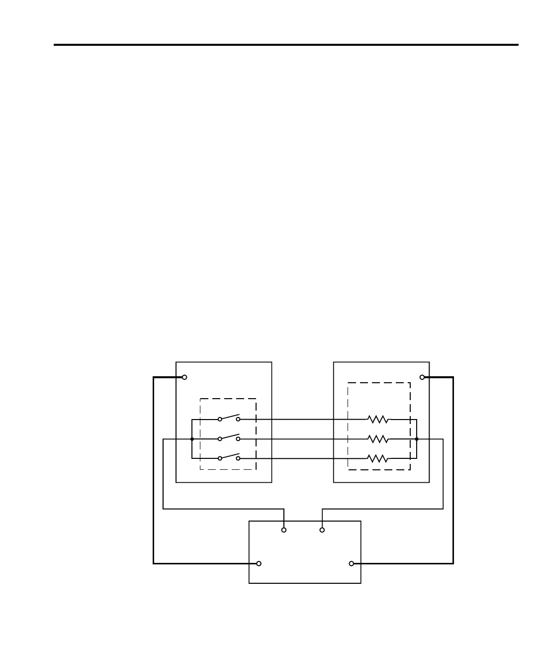
Figure 11-8 shows a basic binning system to test three-element resistor networks. Note that
this system requires a scanner card that is installed in a switching mainframe. Scanner card
switching is controlled through the Trigger Link. End binning control is required for this test
system, therefore, the grading mode must be used.
Trigger operations for the scanner and SourceMeter must be configured appropriately for
this test. In general, the scanner must be configured to scan three channels, and the Source-
Meter must be configured to perform a 3-point sweep and output a trigger to the scanner after
each measurement. See Section 10 for details.
When the testing process is started, Ch 1 of the scanner card closes, and R1 is measured.
Two events occur concurrently after the measurement is completed: R1 is tested, and the
SourceMeter sends a trigger pulse to the switching mainframe causing Ch 1 to open and Ch 2
to close. Assuming there is no failure, a measurement is then performed on R2. While R2 is
being tested, Ch 2 opens and Ch 3 closes. Again assuming no failure, a measurement is per-
formed on R3 and it is then tested. Assuming that all the tests on all three resistors passed, the
device package is placed in the pass bin.
If any of the resistors in the network fails a test, the FAIL message is displayed, and the dig-
ital output information for the first failure is stored in memory (assuming that END binning
control is selected). After the sweep is completed, the SourceMeter sends the output pattern
stored in memory. This is the output pattern for the first test failure. The component handler
places the DUT package into the bin assigned to that particular failure.
The handler selects the next resistor network, and the testing process is repeated.
Switching Mainframe Handler
Trigger
Link
Scanner Card
Ch 1
Ch 2
Ch 3
Dig
In
Multi-Element
Device Package
R1
R2
R3
In/Out
HI LO
Trigger
Link *
Dig
I/O
6430
* Trigger layer configured to output trigger pulse after each measurement.
Figure 11-8
Binning system -
multiple element
devices