F-14 Measurement Considerations
General measurement considerations
The following measurement considerations apply to all precision measurements.
Ground loops
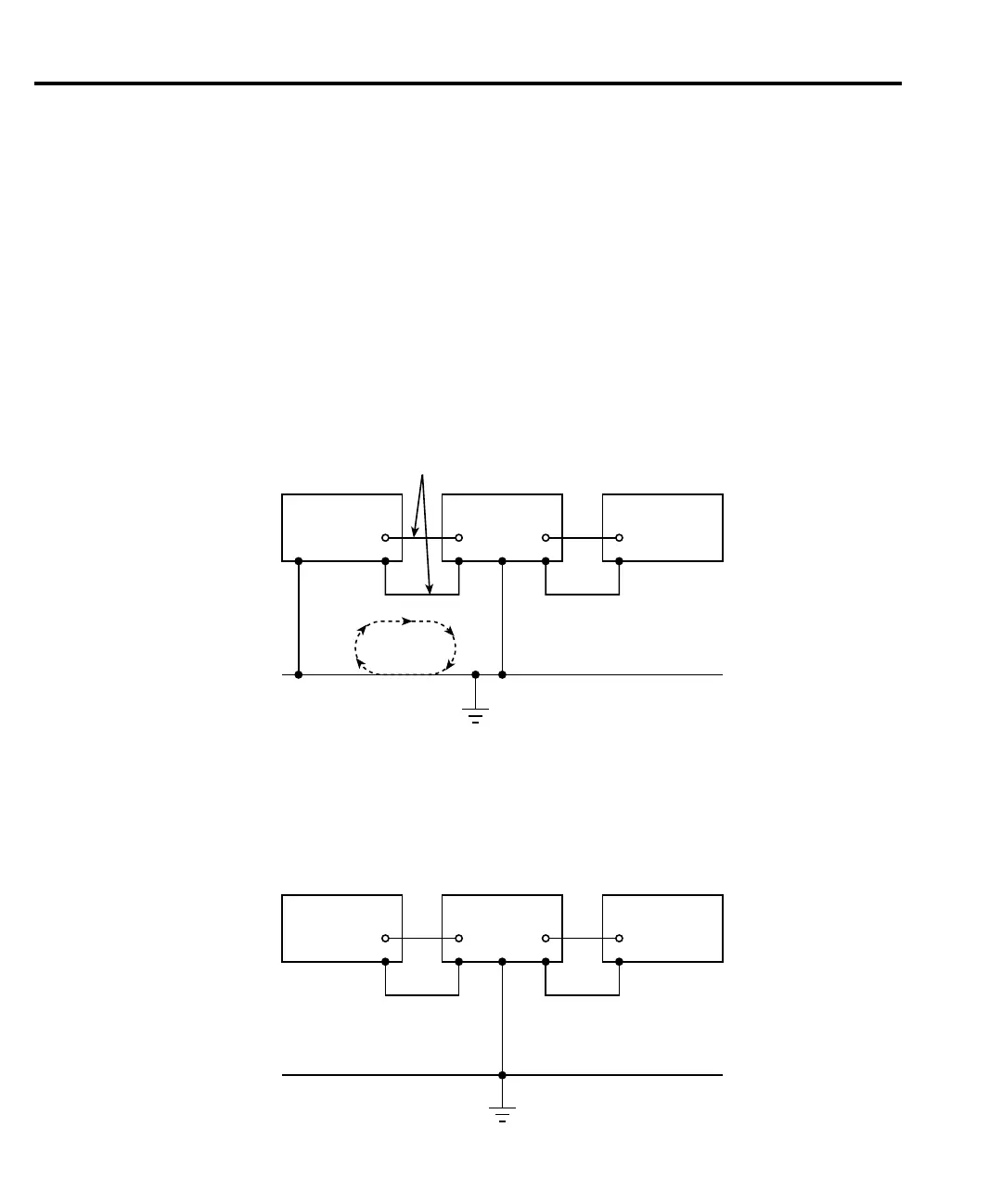
Ground loops that occur in multiple-instrument test setups can create error signals that cause
erratic or erroneous measurements. The configuration shown in Figure F-8 introduces errors in
two ways. Large ground currents flowing in one of the wires will encounter small resistances,
either in the wires, or at the connecting points. This small resistance results in voltage drops
that can affect the measurement. Even if the ground loop currents are small, magnetic flux cut-
ting across the large loops formed by the ground leads can induce sufficient voltages to disturb
sensitive measurements.
To prevent ground loops, instruments should be connected to ground at only a single point,
as shown in Figure F-9. Note that only a single instrument is connected directly to power line
ground. Experimentation is the best way to determine an acceptable arrangement. For this pur-
pose, measuring instruments should be placed on their lowest ranges. The configuration that
results in the lowest noise signal is the one that should be used.
Instrument 1 Instrument 2 Instrument 3
Signal Leads
Ground
Loop
Current
Power Line Ground
Figure F-8
Power line ground loops
Instrument 1 Instrument 2 Instrument 3
Power Line Ground
Figure F-9
Eliminating
ground loops

 Loading...


