Digital I/O Port, Interlock, and Output Configuration 12-3
EOT/BUSY line
Line 4 can be used for a normal bit pattern, EOT (End-of-Test), or BUSY signal, depending
on the selected END OF TEST mode.
NOTE See Section 11 for details on performing limit tests and Section 10 for information
on programming the SourceMeter to respond to the SOT (start-of-test) pulse from a
handler.
+5V output
The Digital I/O Port provides a +5V output that can be used to drive external logic circuitry.
Maximum current output for this line is 300mA. This line is protected by a self-resetting fuse
(one hour recovery time).
Digital output configuration
There are two basic methods to connect external components to the digital output lines, sink
operation and source operation.
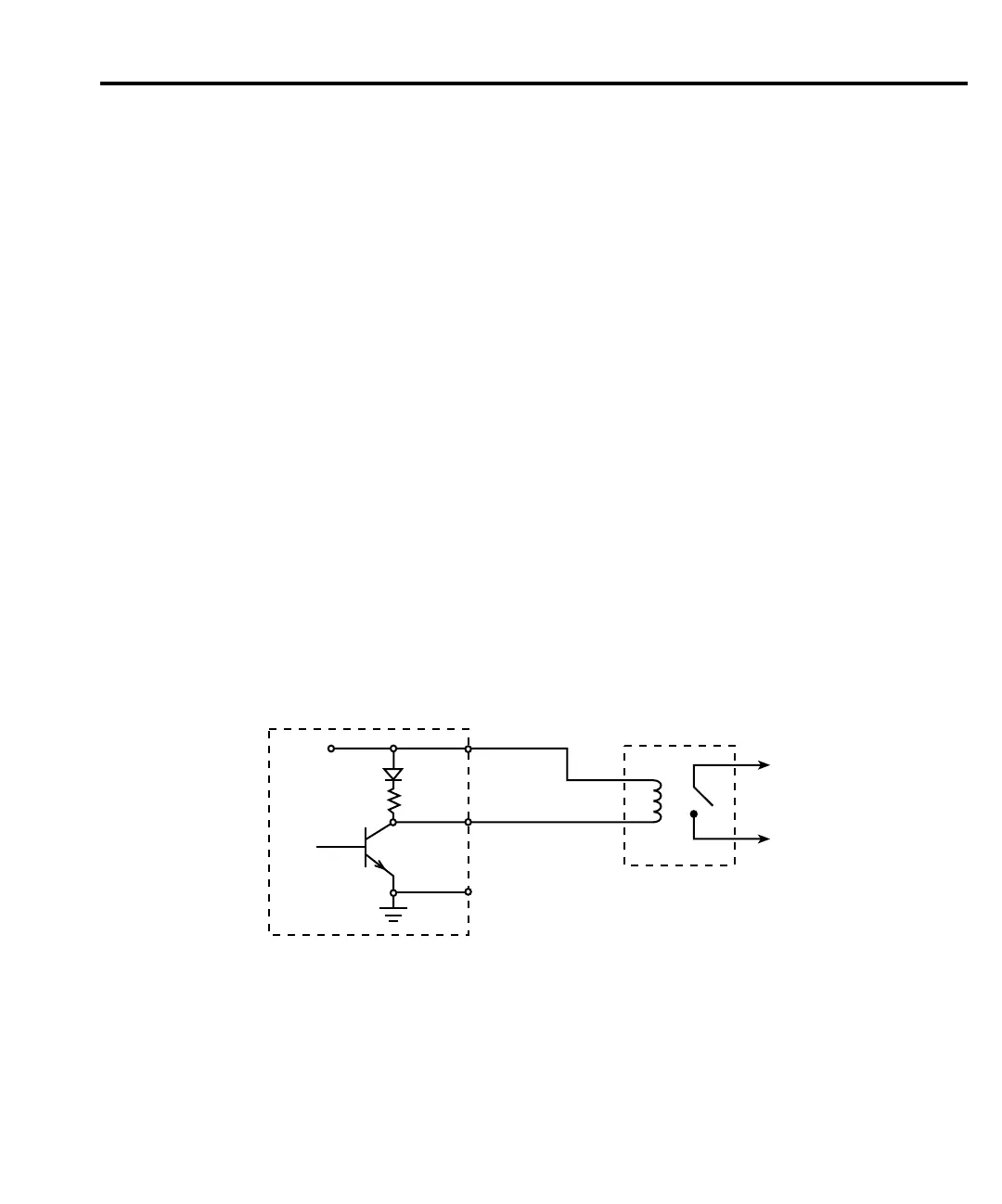
Sink operation
Figure 12-2 shows the basic output configuration for sink operation. Note that the external
relay coil is connected between the digital output line (pins 1 to 4) and +5V (pin 7). With this
configuration, the digital output line must be set LO to energize the relay, and the maximum
sink current is 500mA.
SourceMeter External
Relay
To other
Circuits
+5V
Maximum sink current: 500mA
Pin 7
Pins 1-4
Pin 9
Digital I/O
Port
Figure 12-2
Sink operation
 Loading...


