Limit Testing 11-15
Configuring and performing limit tests
Configuring limit tests
Press CONFIG and then LIMITS to display the CONFIG LIMITS MENU. The limits con-
figuration menu is structured shown below and in Figure 11-10. The limits configuration menu
is structured as follows. Note that bullets indicate the primary items of the limit menu and
dashes indicate the options of each menu item. Refer to Section 1, Rules to navigate menus to
configure the limit tests.
• DIGOUT — Use this menu item to control the following Digital I/O aspects:
- SIZE — Use to select 3-BIT or 4-BIT Digital I/O bit size (or 16-BIT with 2499-
DIGIO opion). In the 3-BIT mode, Digital I/O line 4 becomes the EOT, /EOT,
BUSY, or /BUSY signal depending on the selected END OF TEST mode. In the 4-
BITmode, Digital I/O line 4 is controlled manually if the END OF TEST mode is
set to EOT.
- MODE — Use to select GRADING or SORTING mode. In GRADING mode, a
reading passes if it is within all of the HI/LO limit tolerances enabled, assuming
that it has passed the Compliance tests first. The Digital I/O will be driven with the
first pattern of the first Compliance, HI, or LO failure. Otherwise, the pass pattern
will be output. In GRADING mode, you will also choose bin control modes. With
IMMEDIATE, the testing process will stop after the first failure and place the fail
pattern on the digital output. If none of the limit tests fail, the pass pattern will be
placed on the output, and the testing process will stop. With END, the testing pro-
cess will continue until the programmed sweep is completed, regardless of how
many failures occur. This allows multi-element devices (i.e., resistor networks) to
be tested. After testing is finished, the bit pattern for the first failure is placed on
the output. If all tests pass, the pass pattern will instead be placed on the output.
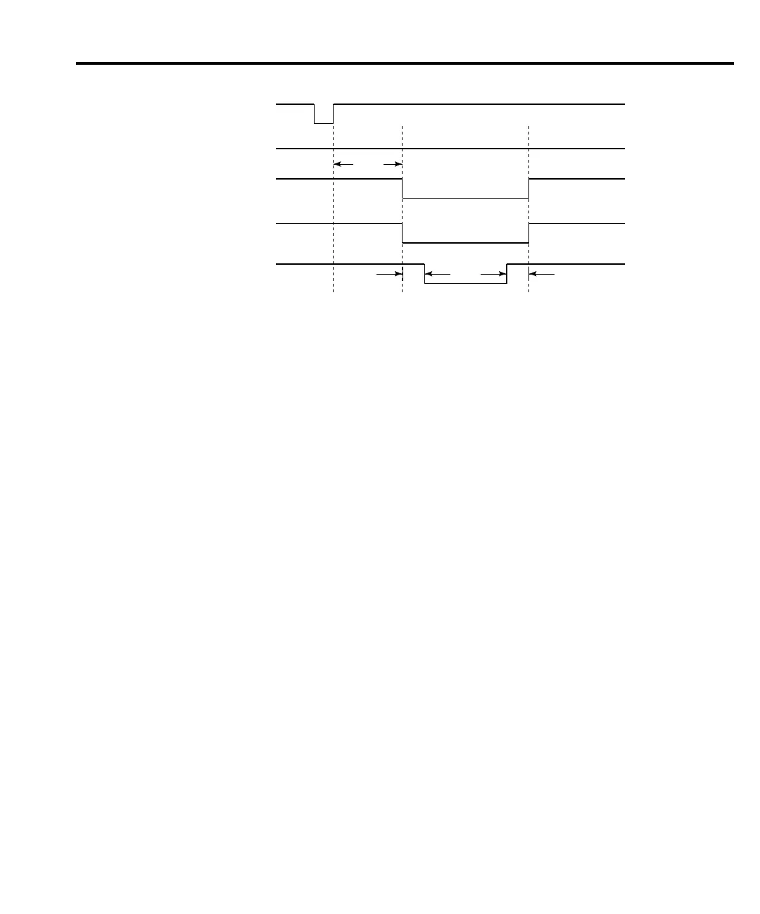
SOT*
Line 1
Line 2
Line 3
Line 4
/EOT (3-bit mode)
10µs 10µs
Delay
*
With the SOT line being pulsed low (as shown), ⇓STEST must be the selected arm
event for the trigger model. If the SOT line is instead pulsed high by the handler,
⇑STEST must be the selected arm event.
Meas.
igure 11-9
igital output
auto-clear timing
example

 Loading...


