10-8 Triggering
Trigger link
Input and output triggers are received and sent via the rear panel TRIGGER LINK connec-
tor. The trigger link has four lines. At the factory, line #2 is selected for output triggers, and line
#1 is selected for input triggers. These input/output line assignments can be changed from the
CONFIGURE TRIGGER menu. See Configuring triggering later in this section. The connector
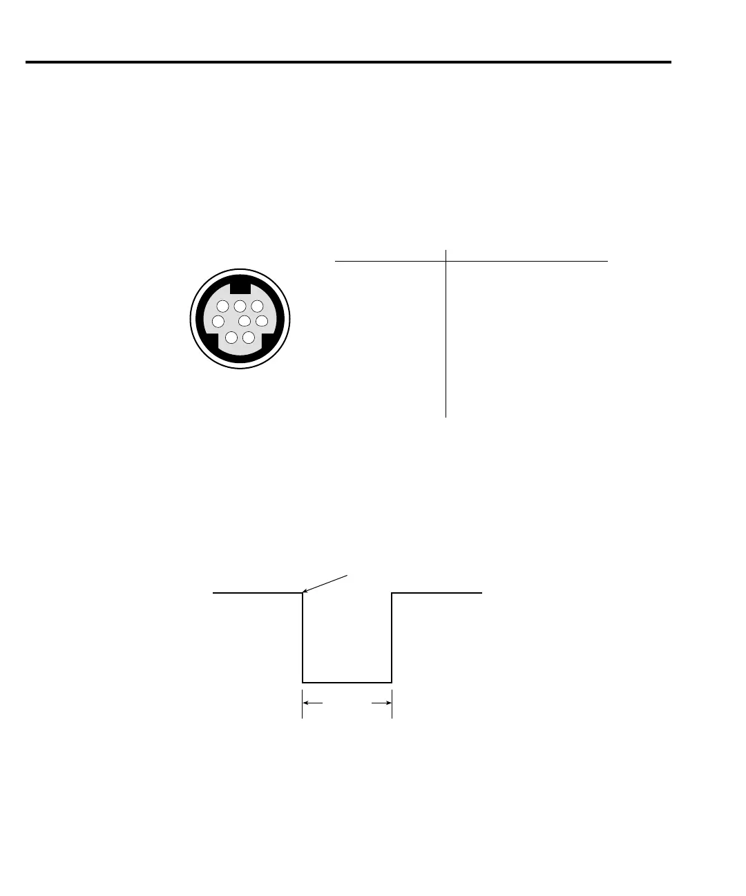
pinout is shown in Figure 10-2.
Input trigger requirements
An input trigger is used to satisfy event detection for a trigger model layer that is configured
for the TRIGGER LINK event. See Trigger model. The input requires a falling-edge, TTL com-
patible pulse with the specifications shown in Figure 10-3.
8 7 6
5
4 3
2 1
Rear Panel Pinout
Pin Number
Description
1
2
3
4
5
6
7
8
Trigger Link 1
Trigger Link 2
Trigger Link 3
Trigger Link 4
Trigger Link 5 (not used)
Trigger Link 6 (not used)
Ground
Ground
gure
-
ear panel pinout
TTL High
(2V – 5V)
Triggers on
Leading Edge
TTL Low
(≤0.8V)
10µs
Minimum
gure
-
Trigger link input pulse
specifications

 Loading...


