Digital I/O Port, Interlock, and Output Configuration 12-7
Front panel output configuration
The output is configured from the CONFIGURE OUTPUT menu and is structured as fol-
lows. Note that bullets indicate the primary items of the sweep menu, while dashes indicate
options. Use Section 1, Rules to navigate menus to check and/or change operate options.
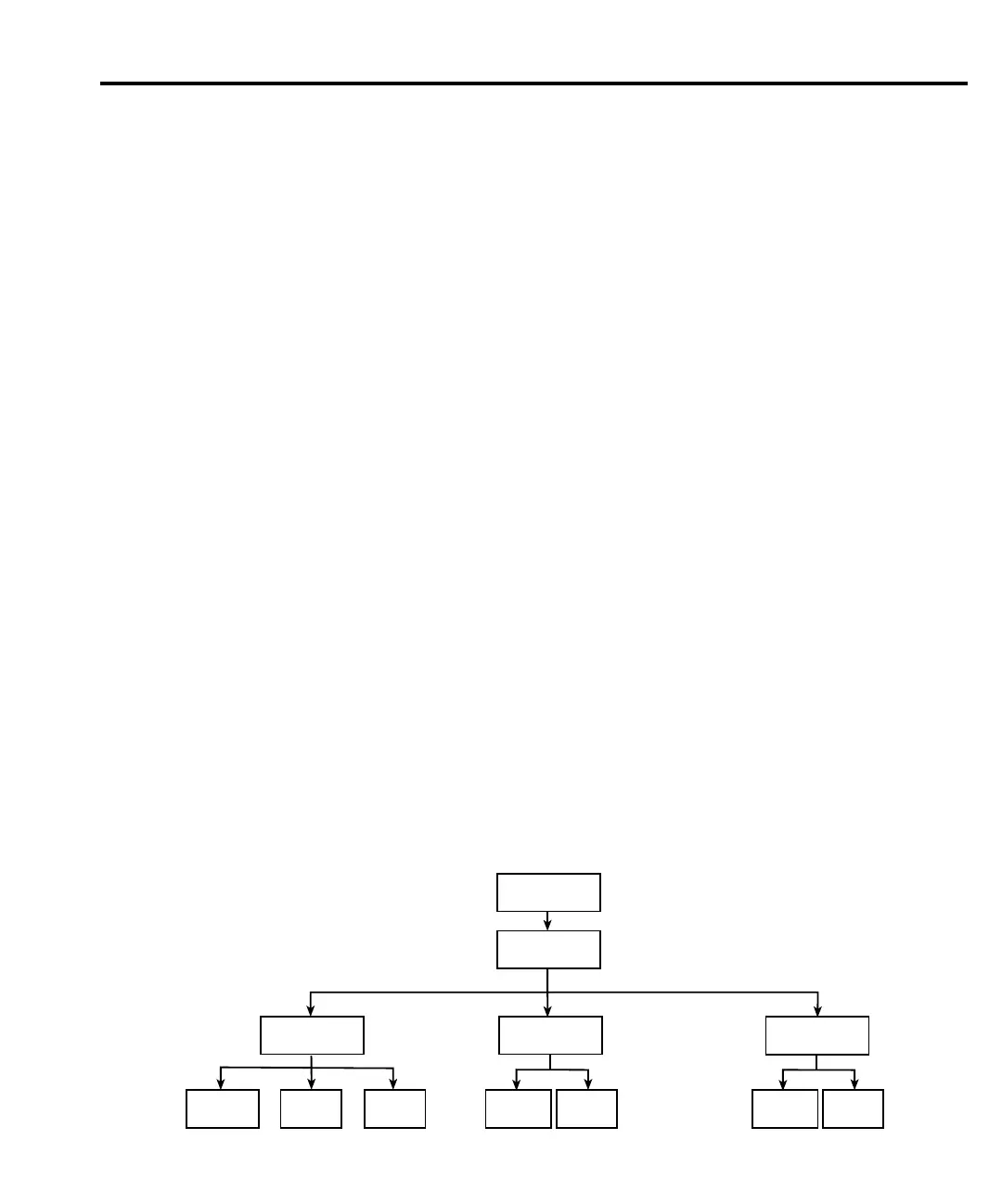
Configure OUTPUT menu
Press CONFIG and then ON/OFF OUTPUT to display the menu, which is also shown in
Figure 12-5.
• OFF STATE — Use to select the OFF state of the output. (See Output-off states for
details.)
- NORMAL — When the OUTPUT is turned off, the V-Source is selected and set to
0V. Current compliance is set to 0.5% full scale of the present current range.
NORMAL is the default off-state.
- ZERO — When the V-Source OUTPUT is turned off, the V-Source is set to 0V
and current compliance is not changed. When the I-Source OUTPUT is turned off,
the V-Source mode is selected and set to 0V. Current compliance is set to the pro-
grammed Source I value or to 0.5% full scale of the present current range, which-
ever is greater. Measurements are performed and displayed while the OUTPUT is
off.
- GUARD — When OUTPUT is turned OFF, the current source is selected and set
to 0A. Voltage compliance is set to 0.5% full scale of the present voltage range.
• AUTO OFF — Use to ENABLE or DISABLE auto output off. When enabled, the
OUTPUT will turn off after the measurement phase of every SDM cycle. The OUTPUT
turns back on at the beginning of the next SDM cycle. When disabled, the OUTPUT
stays on as long as the SourceMeter is operating within the trigger model (ARM annun-
ciator on). With the OUTPUT enabled, pressing the ON/OFF key will disable the OUT-
PUT and disable auto output off.
• INTERLOCK — Use to ENABLE or DISABLE the interlock line of the Digital out-
put. This line is used as an interlock for a test fixture. See Safety interlock.
CONFIG
ON/OFF
OUTPUT
INTERLOCK
ENABLEDISABLE
OFF STATE AUTO OFF
ENABLE
DISABLENORMAL ZERO GUARD
gure
-
Output configuration
menu tree

 Loading...


