C-2 Data Flow
Introduction
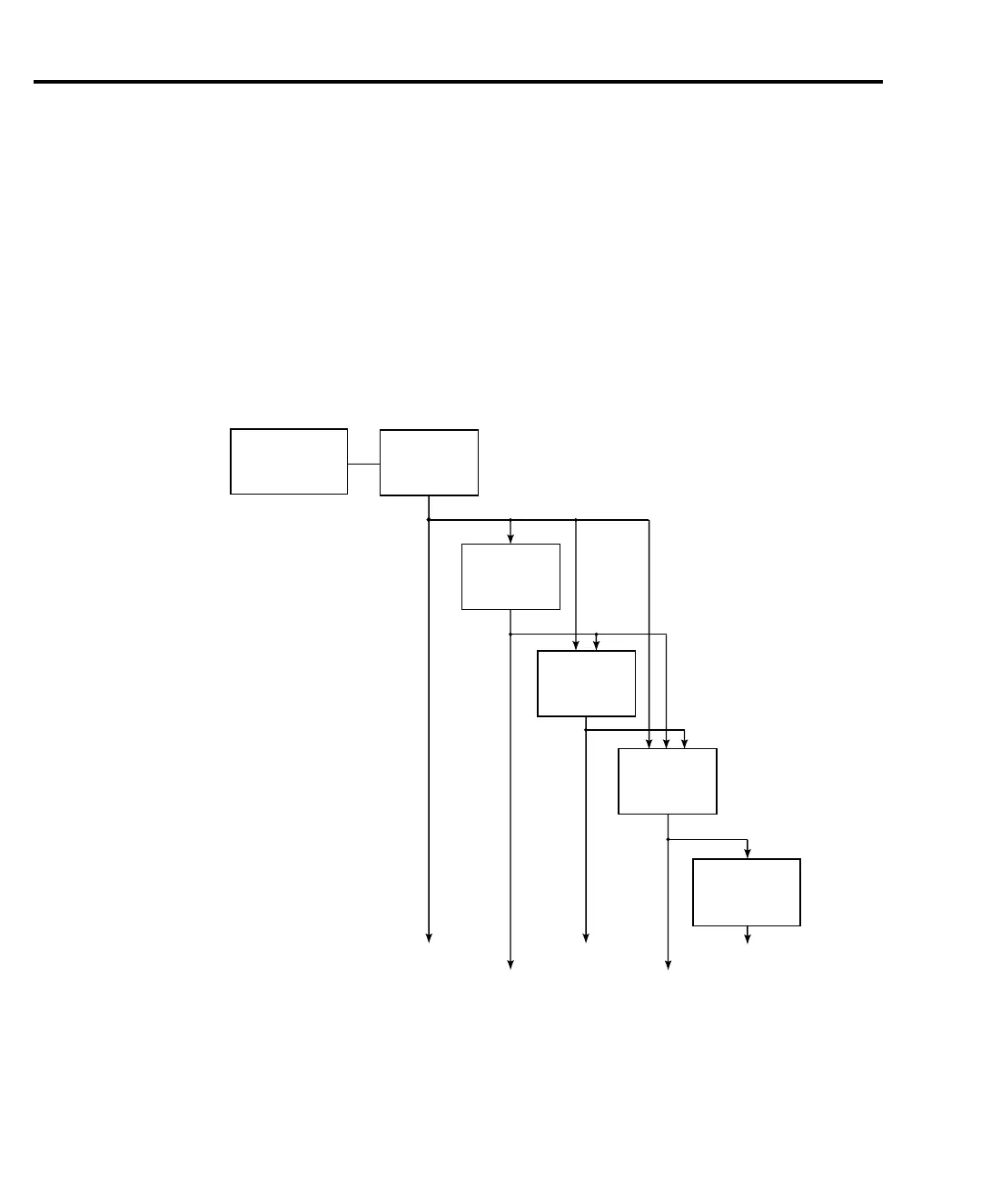
Data flow for remote operation is summarized by the block diagram shown in Figure C-1.
Refer to this block diagram for the following discussion.
The SENSE block represents the basic measured readings of voltage, current and resistance.
If Filter is enabled, the readings will be filtered. The SENSE block also measures time for the
timestamp.
When the INITiate command is sent, the programmed number of source-measure operations
are performed and the respective data is temporarily stored in the Sample Buffer. For example,
if 20 source-measure operations were performed, then 20 sets of data will be stored in the Sam-
ple Buffer. Data from this buffer is then routed to other enabled data flow blocks.
SENSE
(Measurements)
Volts, Amps, Ohms,
Timestamp, Filter
Sample
Buffer
CALC1
Math
Expression
CALC2
Limit Tests
NULL (Rel)
Trace
(Data Store)
FETCh?
READ?
MEAS?
CALC1:DATA?
CALC2:DATA? CALC3:DATA?
TRACe:DATA?
CALC3
Min, Max, Sdev
Mean, Pk-Pk
igure C-1
ata flow block
diagram

 Loading...


