EasyManua.ls Logo

Keithley 6430 User Manual

Keithley 6430
558 pages
To Next Page IconTo Next Page
To Previous Page IconTo Previous Page
Page #250 background imageLoading...
Page #250 background image
12-2 Digital I/O Port, Interlock, and Output Configuration
Digital I/O port
The SourceMeter has a digital input/output port that can be used to control external digital
circuitry, such as a handler that is used to perform binning operations when testing limits.
Port conguration
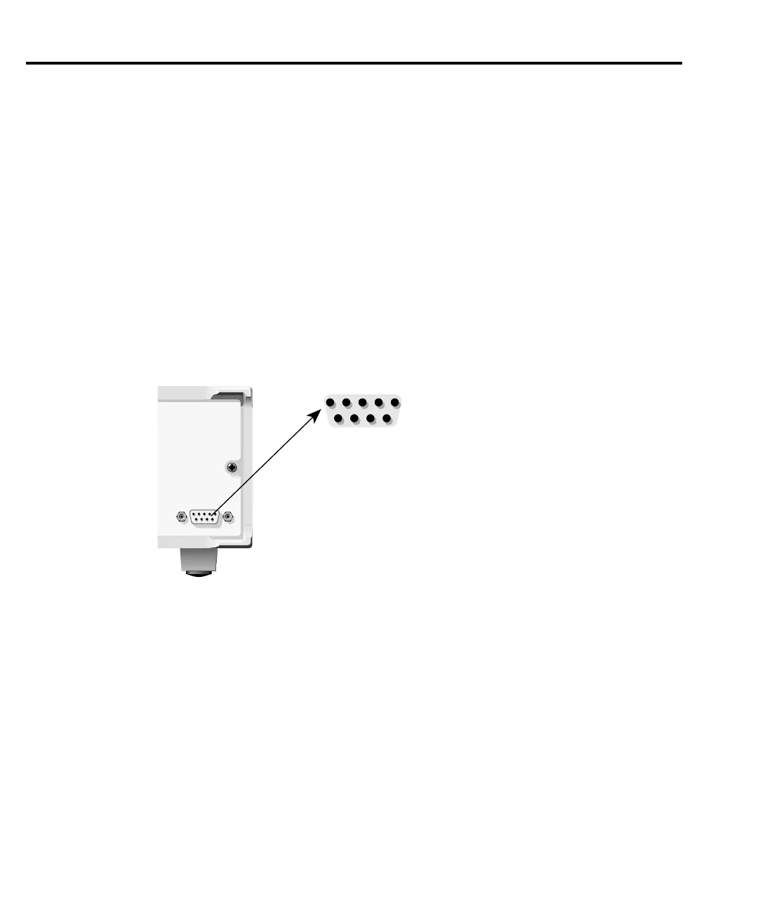
The Digital I/O Port is located on the rear panel and is shown in Figure 12-1. Note that a
standard male DB-9 connector is used for the Digital I/O port.
NOTE The four digital output lines and the SOT line are primarily intended for limit testing
with a device handler. See “Limit testing” in Section 11 for details on performing
limit tests and interfacing to handlers and “Triggering” in Section 10 for informa-
tion on programming the SourceMeter to respond to the SOT (start-of-test) pulse
from a handler.
Digital output lines
The port provides four output lines and one input line. Each open-collector output can be set
high (+5V) or low (0V). Each output line can source up to 2mA or sink up to 500mA. When
using a category register handler for limit testing, output line #4 is typically used for the EOT
(End-of-Test) or BUSY pulse. This pulse from the SourceMeter signals the handler to perform
the binning operation, or indicates a busy condition. (See Section 11, Configuring limit tests.)
SOT line
The input line (SOT) is used by the handler to start limit testing. With the STEST arm
event selected, the handler must pulse SOT low in order to provide event detection which starts
the testing process. With the STEST arm event selected, the handler must pulse SOT high in
order to provide event detection and start the testing process. With the ↑↓STEST arm event
selected, the handler must pulse SOT either high or low in order to provide event detection and
start the testing process.
ONLY.
ONLY.
D RATING.
D RATING.
INTERLOCK-
DIGITAL I/O
SourceMeter
1 5
6 9
1 = Digital Output #1
2 = Digital Output #2
3 = Digital Output #3
4 = Digital Output #4 (EOT, /EOT, BUSY, /BUSY)
5 = Ground
6 = Trigger Input (SOT)
7 = +5V
8 = /Interlock
9 = Ground
Figure 12-1
Interlock and
digital I/O port

Table of Contents

Other manuals for Keithley 6430

Question and Answer IconNeed help?

Do you have a question about the Keithley 6430 and is the answer not in the manual?

Keithley 6430 Specifications

General IconGeneral
TypeSub-Femtoamp Remote SourceMeter
Compliance Voltage200 V
Maximum Output Voltage200 V
Maximum Output Current100 mA
Compliance LimitProgrammable
InterfaceGPIB, RS-232
Input Impedance>10^14 Ω

Summary

Safety Precautions

3 Basic Source-Measure Operation

Basic Source-Measure Procedure

Details setup for source-measure operations: function, values, limits, and output control.

5 Source-Measure Concepts

Compliance limit

Discusses compliance limits, values, and determination.

Operating boundaries

Covers voltage/current boundaries for source, sink, I-source, V-source, and source-measure modes.

6 Range, Digits, Speed, and Filters

Range and digits

Discusses available ranges, limits, manual/autoranging, and display resolution.

Filters

Provides information on 3-stage filtering to reduce reading noise.

7 Relative and Math

Math Operations

Details math (FCTN) operations: power, offset ohms, varistor, etc.

9 Sweep Operation

Configuring and Running a Sweep

Discusses setup, configuration, delay setting, and performing sweeps.

10 Triggering

Trigger Model

Discusses trigger model, layers, event detection, delay, and device action.

Configuring Triggering

Details how to configure various triggering aspects.

Remote Triggering

Details remote trigger model, commands, and basic triggering example.

11 Limit Testing

Types of Limits

Discusses three limit types: compliance, coarse, fine; summarizes grading and sorting modes.

Configuring and Performing Limit Tests

Describes configuration for limit tests and typical test procedure.

12 Digital I/O Port, Interlock, and Output Configuration

Safety Interlock

Describes using Digital I/O Port as a safety interlock.

14 Status Structure

Status Byte and Service Request (SRQ)

Explains programming Status Byte for SRQs and using serial poll to detect SRQs.

15 Common Commands

Command Summary

Lists IEEE-488.2 common commands used by the SourceMeter.

Command Reference

Provides detailed reference for common commands, excluding status structure.

16 SCPI Signal-Oriented Measurement Commands

Configuring Measurement Function

Provides detailed info on commands to configure measurement function.

Acquiring Readings

Describes commands to acquire post-processed readings, trigger, acquire, and single measurement.

17 SCPI Command Reference

18 Performance Verification

Performing the Verification Test Procedures

Details restoring factory defaults, setting ranges, and output values.

Mainframe Verification

Covers procedures to verify mainframe accuracy alone.

19 Calibration

Mainframe Calibration

Includes procedures to calibrate the mainframe without the Remote PreAmp.

20 Routine Maintenance

Line Fuse Replacement

Covers procedure and part numbers for replacing the line fuse.

F Measurement Considerations

Floating measurement safety concerns

Discusses safety concerns for measurements up to 42V above chassis ground.

Leakage currents and guarding

Explains reducing leakage currents using insulators, humidity control, and guarding.

Related product manuals