6-16 Source-Measure Concepts 2400 Series SourceMeter
®
User’s Manual
Model 2410 SourceMeter
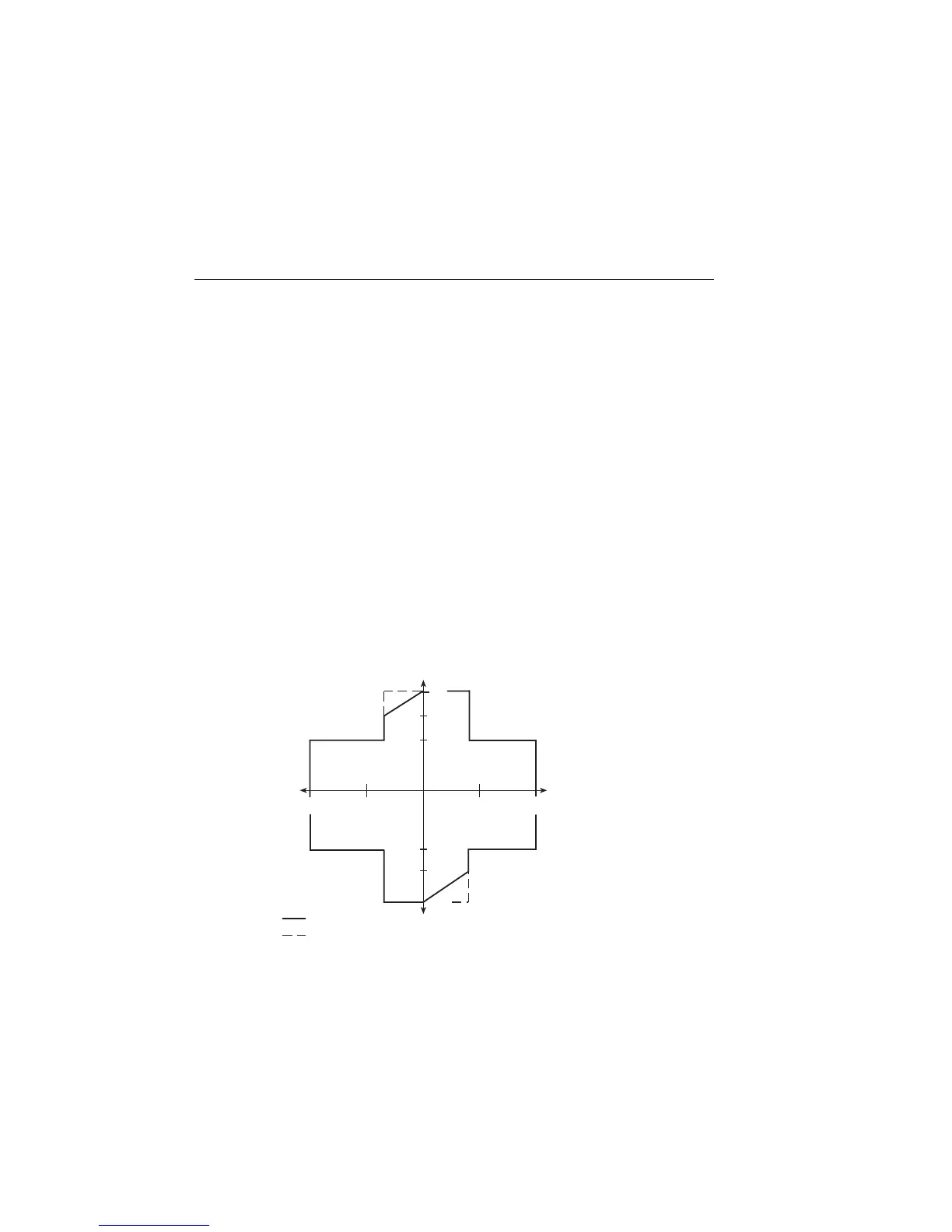
The general operating boundaries for the Model 2410 are shown in Figure 6-5. In this
drawing, the 1A, 20V and 20mA, 1kV magnitudes are nominal values. The actual maxi-
mum output magnitudes of the SourceMeter are 1.05A, 21V and 21mA, 1.1kV. Also note
that the boundaries are not drawn to scale.
These operating boundaries are valid only if the SourceMeter is being operated in an envi-
ronment where the ambient temperature is 30˚C or less.
NOTE Above 30˚C, high power operation could overheat the SourceMeter, causing the
output to turn off. See “Overheating protection,” page 6-6, and “Power equa-
tions to avoid shutdown,” page 6-7, for details.
The heavy solid lines show the limits for continuous output operation. Note that in quad-
rants II and IV (sink operation), the limits for the 1A range are derated as follows:
1A Range – Limits linearly derated from: -1A, 20V to -0.6A, 20V
1A, -20V to 0.6A, -20V
If the output duty cycle is decreased to 60% or less, sink operation limits are restored to
normal as shown by the dotted lines in Figure 6-5. (The 40% off time allows a sufficient
cooling period.)
Figure 6-5
Model 2410 operating boundaries (T
amb
≤
30°C)
–I
= 100% Duty Cycle
≤ 60% Duty Cycle
(III)
Source
–V
+V
+I
(IV)
Sink
(II)
Sink
(I)
Source
1A
600mA
-600mA
-1A
-1kV
-20V
20V
1kV
20mA
-20mA
Artisan Technology Group - Quality Instrumentation ... Guaranteed | (888) 88-SOURCE | www.artisantg.com
 Loading...