13-2 Digital I/O Port, Safety Interlock, and Output Configuration 2400 Series SourceMeter
®
User’s Manual
Digital I/O port
The SourceMeter has a digital input/output port that can be used to control external digital
circuitry, such as a handler that is used to perform binning operations when testing limits.
NOTE For the Model 2400 only, the Digital I/O connector is marked output enable.
Port configuration
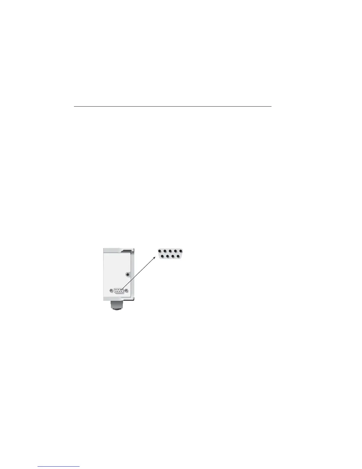
The Digital I/O Port is located on the rear panel and is shown in Figure 13-1.
NOTE The four digital output lines and the SOT line are primarily intended for limit
testing with a device handler. See Section 12, “Limit Testing,” for details on per-
forming limit tests and interfacing to handlers and Section 11, “Triggering,” for
information on programming the SourceMeter to respond to the start-of-test
(SOT) pulse from a handler.
Figure 13-1
Digital I/O port
Digital output lines
The port provides four output lines. Each open-collector output can be set high (+5V) or
low (0V). Each output line can source up to 2mA or sink up to 500mA. When using a cat-
egory register handler for limit testing, output line #4 is typically used for the end-of-test
(EOT) or BUSY pulse. This pulse from the SourceMeter signals the handler to perform the
binning operation, or indicates a busy condition. (See Section 12, “Configuring limit
tests.”)
INTERLOCK-
DIGITAL I/O
SourceMeter
15
69
1 = Digital Output #1
2 = Digital Output #2
3 = Digital Output #3
4 = Digital Output #4 (EOT, /EOT, BUSY, /BUSY)
5 = Ground
6 = Trigger Input (SOT)
7 = +5V
8 = /Interlock
9 = Ground
Note: Connector marked OUTPUT ENABLE
on Model 2400.
Artisan Technology Group - Quality Instrumentation ... Guaranteed | (888) 88-SOURCE | www.artisantg.com
 Loading...