2400 Series SourceMeter
®
User’s Manual Sweep Operation 10-23
For the purposes of this test, assume the following basic sweep parameters:
Source Function: current
Sense Function: volts
Source Mode: sweep
Start Current: 1mA
Stop Current: 10mA
Step Current: 1mA
Voltage Compliance: 1V
Source Delay: 100ms
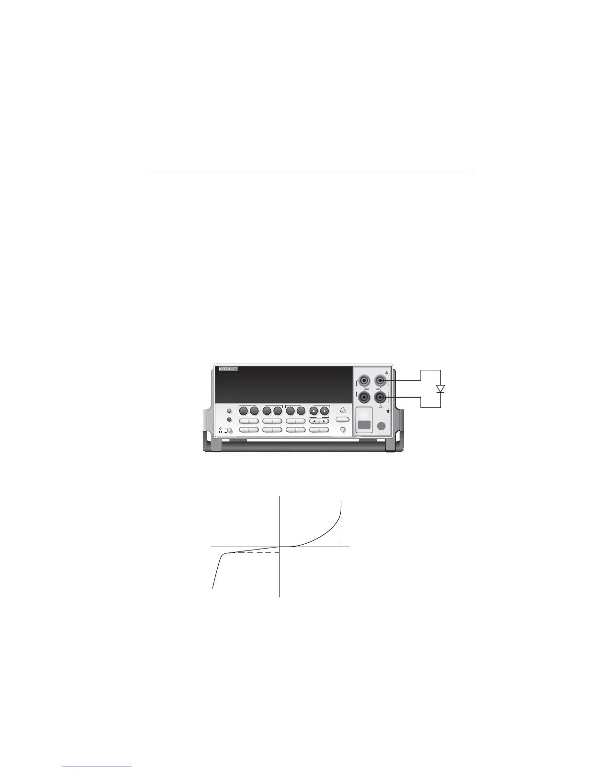
Figure 10-8 shows typical test connections for this test, and Figure 10-9 shows a typical
diode curve. Note that the diode anode is connected to INPUT/OUTPUT HI, and the cath-
ode is connected to INPUT/OUTPUT LO. These connections are required to properly for-
ward bias the diode for the purposes of the test. The test connections could also be
reversed by using negative sweep voltage parameters.
Figure 10-8
Connections for diode I-V tests
Figure 10-9
Diode I-V curve
SourceMeter
250V
PEAK
5V
PEAK
HI
LO
OUTPUT
1100V
PEAK
1100V
PEAK
EDIT
TOGGLE
POWER
RANGE
INPUT/
OUTPUT
4 WIRE
SENSE
DISPLAY
ON/OFF
TERMINALS
FRONT/
REAR
AUTO
RANGE
Diode
Under
Test
!
EXIT ENTER
CONFIG MENU
SWEEP
TRIG
REL
LOCAL
FILTER
LIMIT
DIGITS SPEED
V
Ω
MEAS
I
FCTN
V
I
SOURCE
230
1
67
89
4
+/-
5
STORE
RECALL
EDIT
I
-I
-V
V
I
V
V
reverse
leakage
forward
Artisan Technology Group - Quality Instrumentation ... Guaranteed | (888) 88-SOURCE | www.artisantg.com
 Loading...