GZD15, WSM TRANSAXLE
2-M12
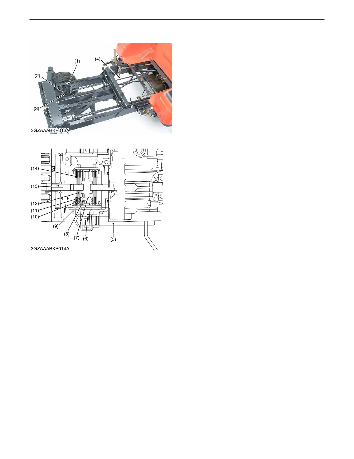
(9) Brake
Brake system is composed of brake pedal, brake
pedal arm (1), brake shaft, parking brake lock lever (2),
brake return spring (3), brake rod (4) located at the
machine front side and brake arm (5), brake lever (6),
actuator (7), balls (8), actuator plate (9), friction plates
(10), brake disks (11), brake plates (12) (14) located at
the machine transmission rear side.
As the parking brake lock pedal is pressed and the
parking brake lock lever (2) is pushed, the brake will be
applied and locked.
When the parking brake is released, the brake can be
released if the parking brake lever is pulled back.
To prevent the brake from dragging when the parking
brake is applied, this machine is designed so that the
engine may stop if the brake pedal is not released within
few seconds after the engine is started.
(1) Brake Pedal Arm (8) Ball
(2) Parking Brake Lock Lever (9) Actuator Plate
(3) Brake Return Spring (10) Friction Plate
(4) Brake Rod (11) Brake Disc
(5) Brake Arm (12) Brake Plate
(6) Brake Lever (13) HST Motor Shaft
(7) Actuator (14) Brake Plate
0000001613E
 Loading...