GZD15, WSM HYDRAULIC SYSTEM
4-M13
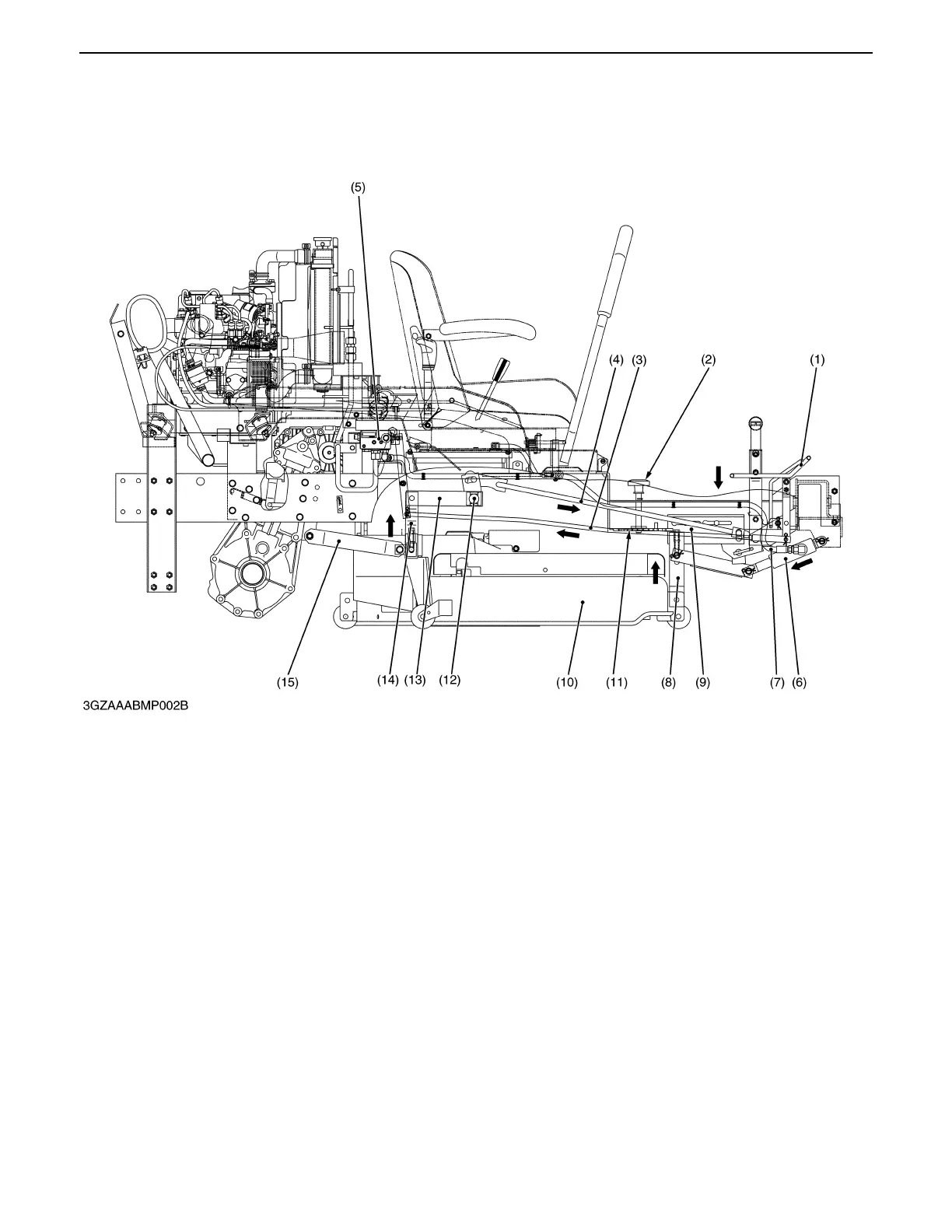
5. MOWER LINKAGE
The mower rear link (14) and rear arm (13) are linked with lift link (2), (12), lift link rear (3), (10) lift link shaft (12)
and mower lift arm (6).
As the hydraulic control pedal (1) moves to up position, front link (8) is raised and lift link shaft (12) is rotated to pull
the rear link (14) to upward. As a result, mower (10) are lifted.
The cutting height adjusting dial (2) adjusts cutting height of mower by rotating the adjusting cam (11). The position
of mower rear link (14) are adjusted by changing the lift rod (4).
(1) Mower Lift Pedal (4) Lift Rod (8) Front Link (12) Lift Link Shaft
(2) Cutting Height Adjusting (5) Control Valve (9) Cam Arm (13) Rear Arm
Dial (6) Lift Cylinder (10) Mower (14) Rear Link
(3) Lift Rod (7) Delivery Hose (11) Adjusting Cam (15) Link Retainer
0000001582E
 Loading...