GZD15, WSM HYDRAULIC SYSTEM
4-M1
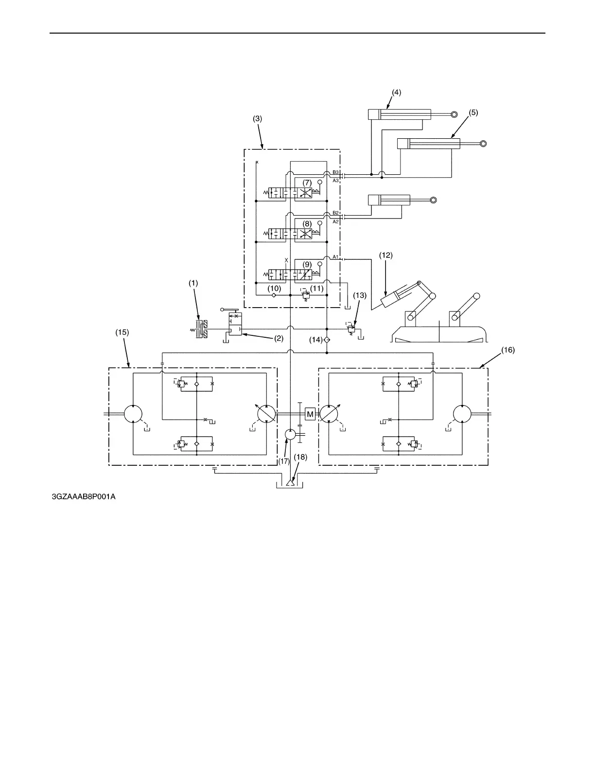
1. HYDRAULIC CIRCUIT
The hydraulic system of this machine is composed of a hydraulic pump (17), control valve assembly (3), grass
collector lift cylinder (4), (5) and other components.
This system has the following functions.
Oil is supplied by hydraulic pump (17) which is driven by engine.
Power from the input shaft (pump shaft) is distributed right and left with the bevel gears and drives each hydrostatic
transmission (15), (16).
Moreover, oil from the hydraulic pump (17) is sent to the transmission centre case through the control valve. On
the other hand, oil is regulated with the regulator valve (13) to constant pressure and sent to the hydrostatic
transmission (15), (16) and PTO clutch (1).
(1) PTO Clutch (5) Grass Collector Lift (8) Grass Collector Dumping (13) Regulator Valve
(2) PTO Clutch Valve Cylinder (LH) Control Valve (14) Oil Filter
(3) Hydraulic Control Valve (6) Grass Collector Dump (9) Mower Lifting Control Valve (15) HST (LH)
Assembly Cylinder (10) Check Valve (16) HST (RH)
(4) Grass Collector Lift (7) Grass Collector Lifting (11) Relief Valve (17) Hydraulic Pump
Cylinder (RH) Control Valve (12) Mower Lift Cylinder (18) Oil Strainer
0000001566E
 Loading...