GZD15, WSM HYDRAULIC SYSTEM
4-S6
(2) Disassembling and Assembling
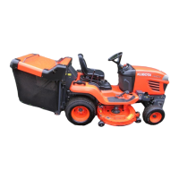
Removing Control Valve
A Since clearance between hydraulic hoses is very narrow.
Thin and narrow open-end spanner 17-19 mm is required.
1. Remove the nuts (1).
2. Remove the control valve and bracket as a unit.
3. Remove the control valve (2) with the control valve adaptor
(3).
4. Remove the control valve adaptor (3) from the control valve
(2).
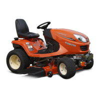
(When reassembling)
A Take care not to damage the hydraulic hoses.
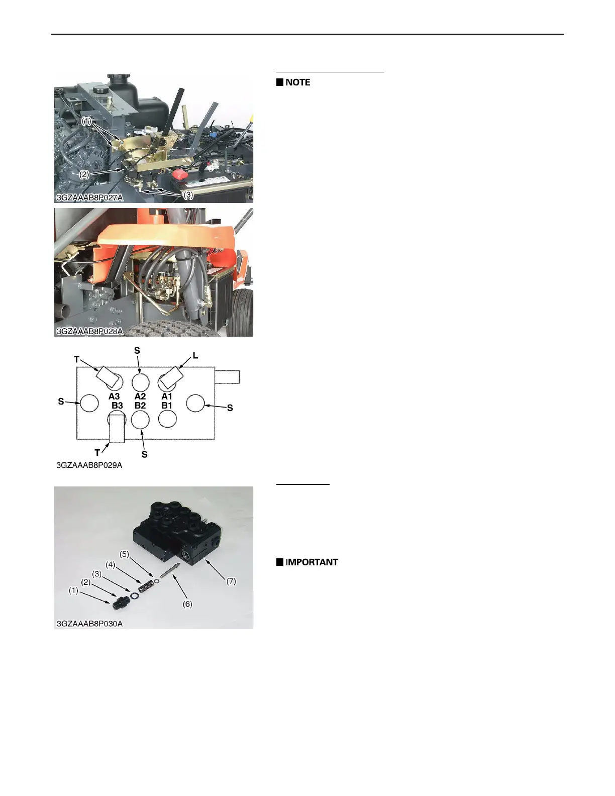
A Install the adaptors, the hydraulic hoses and pipes to the
control valve as the picture and the illustration.
Relief Valve
1. Unscrew the lock nut (2) and the relief adjusting screw (1) from
the control valve (7).
2. Remove the washer (5) spring (4) and valve (6).
(When reassembling)
A Take care not to damage the O-ring (3).
A After reassembling the relief valve, be sure to adjust its
setting pressure. (See page 4-S5.)
(1) Nut A1-B3: Control Valve Port
(2) Control Valve PL: Plug
(3) Adaptor S: Straight Adaptor
(4) Hydraulic Hose L: L Type Adaptor
(5) Hydraulic Pipe T: T Type Adaptor
0000001589E
(1) Adjusting Screw (5) Spring
(2) Lock Nut (6) Valve
(3) O-ring (7) Control Valve
(4) Washer
0000001590E
 Loading...