GZD15, WSM ELECTRICAL SYSTEM
5-S6
[2] STARTING SYSTEM
(1) Checking
Method of Inspecting Each Control
A defective location can be judge by checking function of each
safety switch one by one as shown in the table below.
(Reference)
A Type of Safety Switch
Parking Brake Pedal......Normal Close
Motion Control Lever.....Normal Open
PTO Lever....................Normal Open
Operator's Seat............Normal Open
Grass Collector............Normal Open
A Engine starting condition
Engine is started when the motion control lever (L, R) is set to
"NEUTRAL" position, PTO lever is set to "OFF" position,
operator is sitting on the operator's seat and the brake pedal is
depressed. In other cases, engine is not started.
Connector Voltage
1. Disconnect the main seitch connector (1) from the main switch
(2).
2. Measure the voltage with a voltmeter across the main switch
connector B (Red) terminal and chassis.
3. If the voltage differs from the battery voltage (11 to 14 V), the
wiring harness is faulty.
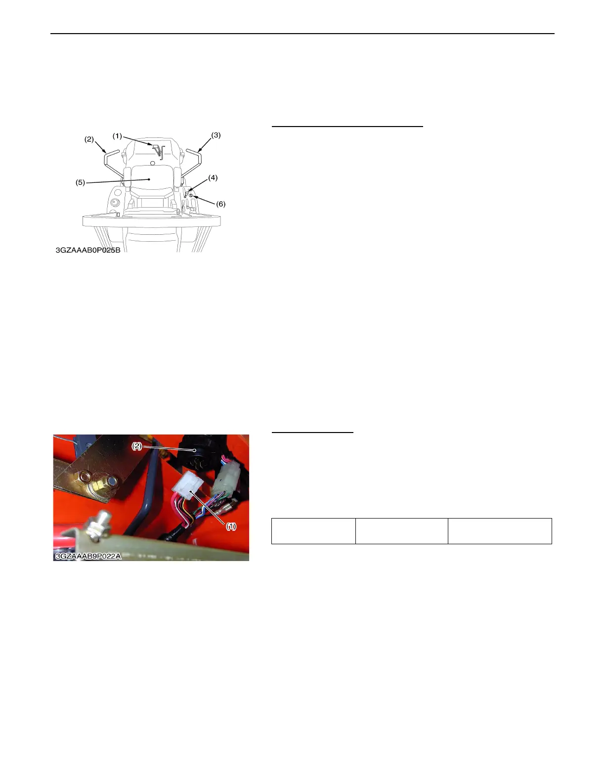
(A) Safety Switches
(1) Parking Brake Pedal (4) PTO Lever
(2) Motion Control Lever (LH) (5) Operator's Seat
(3) Motion COntrol Lever (RH) (6) Key Switch
0000001533E
(B) Main Switch
Voltage
Connector B terminal
- chassis
Approx. battery voltage
(1) Main Switch Connector (2) Main Switch
0000001535E
 Loading...