Installation
4-29
SHB9300CRV EN 2.0
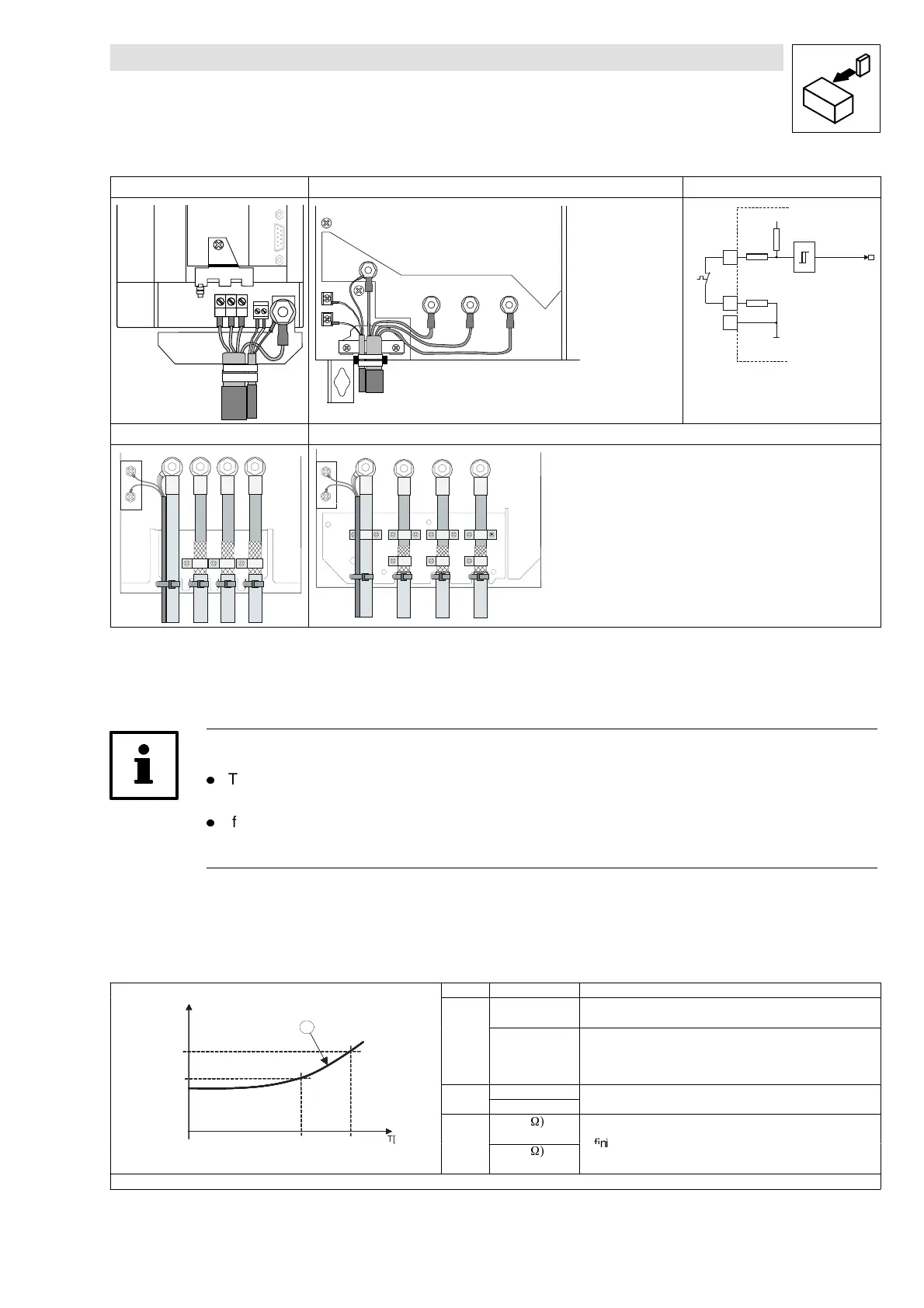
Types 9321 to 9326 Types 9327 and 9330 Internal wiring
UVW
PE
U
V
W
X10
T1 T2
1
5
PE
T1
T2
UVW
MONIT-OH8
T1
T2
7
X6
24 V
93xx
K350052
ϑ
3,3k
7,4k
2,7k
Types 9330 and 9331 Type 9332
T1
T2
PE
UVW
T1
T2
PE
U
VW
Fig. 4-14 Connection of a thermal sensor to the terminals T1 and T2 and interconnection
Note!
l
The pre-cut Lenze system cables for Lenze servo motors provide the cable for the
temperature feedback. The cables are designed for wiring according to EMC.
l
If you use cables of your own:
– Always lay cables separately from motor cables.
4.2.9.1 User-specific characteristic for a PTC resistor
T[°C]
R [Ohm ]
R 2
(C 1192/2)
T 1
(C 1191/1)
R 1
(C 1192/1)
T 2
(C 1191/2)
a
Code Subcode Description
T[°C]
R [Ohm ]
R 2
(C 1192/2)
T 1
(C 1191/1)
R 1
(C 1192/1)
T 2
(C 1191/2)
a
C1190
0
(Control mode 1)
Evaluation of the Lenze standard motor-temperature sensor
T[°C]
R [Ohm ]
R 2
(C 1192/2)
T 1
(C 1191/1)
R 1
(C 1192/1)
T 2
(C 1191/2)
a
1
(Control mode 2)
Evaluation of a user-specific temperature sensor. The operating
level is almost in the linear section (a) of the sensor
characteristic. The working area is determined by two vertex.
Interpolation between these two points.
T[°C]
R [Ohm ]
R 2
(C 1192/2)
T 1
(C 1191/1)
R 1
(C 1192/1)
T 2
(C 1191/2)
a
C1191
1 (100 °C)
Definition of the temperature vertex assigned to the
T[°C]
R [Ohm ]
R 2
(C 1192/2)
T 1
(C 1191/1)
R 1
(C 1192/1)
T 2
(C 1191/2)
a
2 (150 °C)
resistances of the sensor.
T[°C]
R [Ohm ]
R 2
(C 1192/2)
T 1
(C 1191/1)
R 1
(C 1192/1)
T 2
(C 1191/2)
a
C1192
1 (1670
W)
T[°C]
R [Ohm ]
R 2
(C 1192/2)
T 1
(C 1191/1)
R 1
(C 1192/1)
T 2
(C 1191/2)
a
2 (2225
W)
Example of a sensor characteristic for continuous temperature detection
 Loading...