OPERATING CONTROLS AND INDICATORS TMS9000-2 OPERATOR MANUAL
3-96 Published 02-21-2019, Control # 611-05
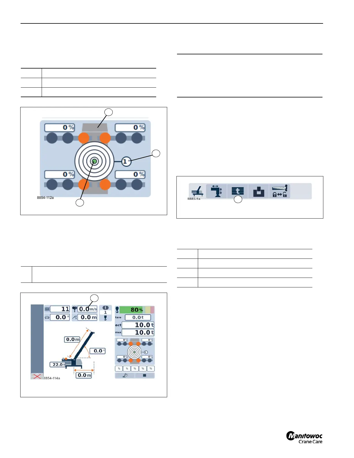
Inclination indicator
On the RCL operating menu
Anemometer display
When the anemometer is connected it will display on the
RCL screen.
V
max
= maximum permissible/reduced wind speed as shown
in the lifting capacity table
Counterweight menu
The rear counterweight support bracket is intended to give
the option to shift weight from the front axles to the rear axles
in a trailing boom configuration only.
The front deck is where the counterweight is assembled and
then installed onto the superstructure.
The counterweight menu is used to add or remove
counterweights to the superstructure.
To open: Select symbol (1, (Figure 3-120)) and confirm.
Counterweight locking display
The current status of the counterweight locking is shown by
different symbols (Figure 3-121):
1 Inclination indicator (Figure 3-118)
2 Measuring range display
3 Directional indicator
1
Display in meters per second (m/sec) or Beaufort
scale (B) (Figure 3-119)
CAUTION
Machine Damage Hazard!
Potential damage to the superstructure if swinging with
the 2268 kg or 1361 kg (5000 lb or 3000 lb) slab sitting on
the rear mounted counterweight support bracket.
1 green – unlocked
2 green – raised
3 yellow – intermediate position
4 red – error

 Loading...


