OPERATING CONTROLS AND INDICATORS TMS9000-2 OPERATOR MANUAL
3-6 Published 02-21-2019, Control # 611-05
Headlights Switch
The headlights switch (1) is a three position switch located
on the top left side of the front console. The bottom position
is off. The center position will illuminate marker, clearance
and gauge lights. The top position will turn on the headlights
in addition to the marker, clearance and gauge lights.
Dimmer Switch
The dimmer switch (2) is located on the left top side of the
front console. The switch controls the brightness of the
gauge lights.
NOTE: The headlight switch (1) must be in the center or
top position before gauge lights will illuminate and
the dimmer switch becomes functional.
Beacon Light Switch (Optional)
The beacon light switch (3) is a two position, on-off switch
located on the left side of the front console that controls the
beacon light on the top of the carrier cab and both
superstructure beacon lights.
Engine Brake On/Off Switch
The engine brake on/off switch is located on the left side of
the front console. The two position (on/off) switch (4)
energizes the engine brake. When the top of the switch is
pushed, the switch is in the on position.
Engine Brake High/Low Switch
The two position engine brake high/low switch (5) controls
the amount of engine braking.
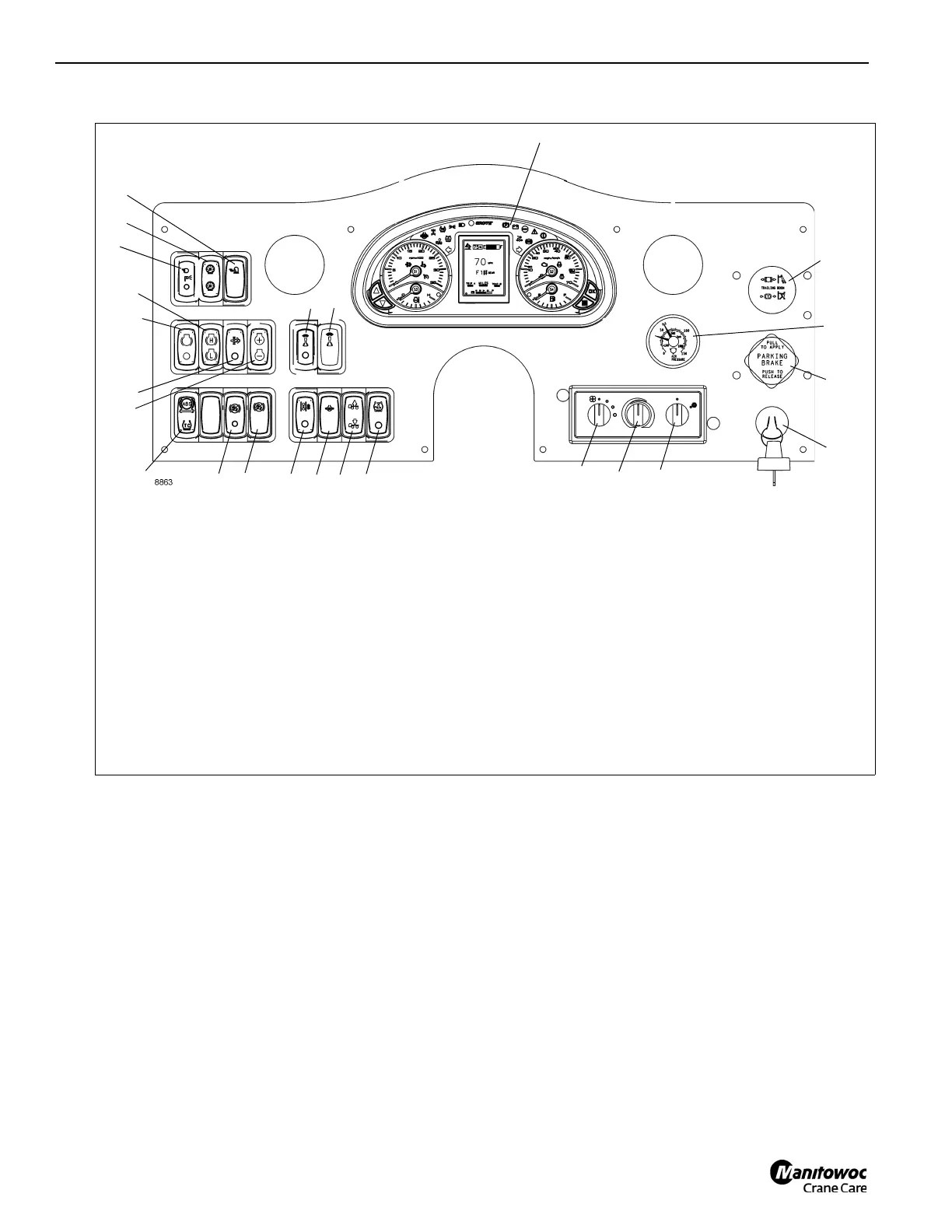
1. Headlights Switch
2. Dimmer Switch
3. Beacon Light Switch (Optional)
4. Engine Brake On/Off Switch
5. Engine Brake High/Low Switch
6. Exhaust System Cleaning Initiate Switch
7. Engine Idle Increment/Decrement Switch
8. Remote Control On/Off Switch
9. Remote Control Indicator
10. ABS/ATC Switch
11. Hill Start Aid (HSA) Switch (Optional)
12. HSA Indicator (Optional)
13. Inter-Axle Lock Switch
14. Cross-Axle Lock Switch (Optional)
15. Suspension Inflation Switch
16. Tire Inflation Switch
17. Heater/Air Conditioner Fan Switch
18. Heater/Air Conditioner Control
19. Heater/Air Conditioner Select Switch
20. Ignition Switch
21. Parking Brake Control
22. Dual Air Pressure Gauge
23. Trailer Air Supply control
(Optional)
24. Control Panel Indicator and Gauge Display
6
18
20
21
22
23
24
3
4
5
1
2
19
17
7
8
FIGURE 3-4
9
10
11
12
13
14 15
16

 Loading...


