SET-UP AND INSTALLATION TMS9000-2 OPERATOR MANUAL
6-86
Published 02-21-2019, Control # 611-05
Removing the Hydraulic Offsetable Heavy
Duty Extension
1. Disconnect the cable from the junction box on the boom
nose.
2. Disconnect the anti-two block switch cable from the
junction box on the extension.
3. Remove the clip (2, Figure 6-180) securing the anti-two
block switch (1) to the pin, and remove the anti-two block
switch.
4. Remove the retaining clip and pin (1, Figure 6-179).
5. Rotate the sheave up into the stowed position
(Figure 6-178).
6. Remove the retaining clip and pin securing the upper
sheave and lower the sheave into the stowed position.
Secure the sheave with the pin and retaining clip.
7. Use the impact driver (3, Figure 6-177) to turn the jack
screw (4) clockwise to remove the pins (5) from the
fittings.
8. Swing the heavy duty extension around to the right side
of the main boom. Engage the extension with the lug on
the main boom.
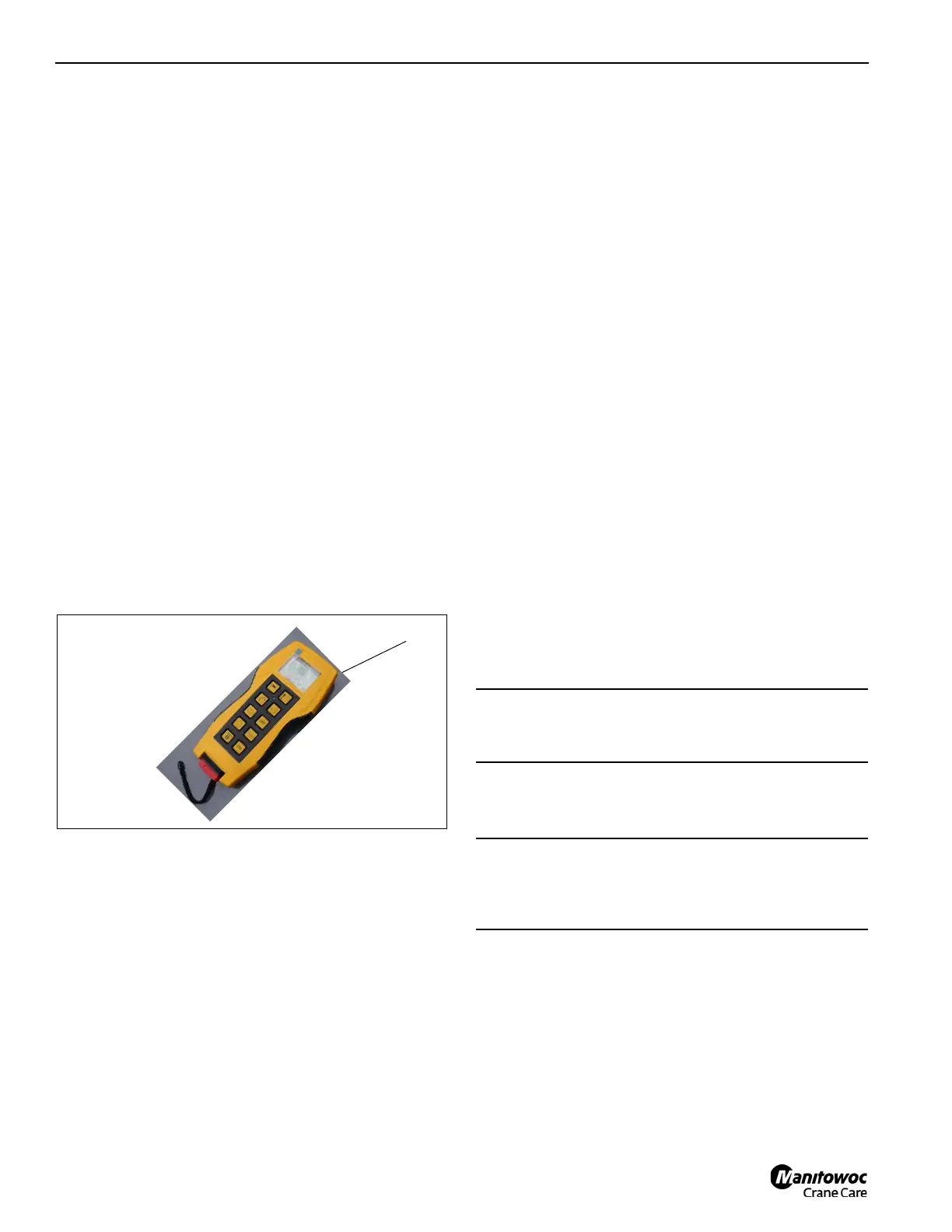
9. Using the remote, (1, Figure 6-181) engage pin #2 (1,
Figure 6-176) with the extension and lug.
10. Use the impact driver to turn the jack screw clockwise to
remove the pins from the extension attachment fittings
and the main boom anchor fittings.
11. Using the remote controller, fully retract the luffing
cylinder. The barrel pointer #2 if equipped, should be
located to line up with the rod pointer when the
extension has boom luffed down enough to clear the
base jib hanging on the boom carrier brackets.
12. Rotate the heavy duty extension slightly to align the
lattice base extension fittings with the heavy duty
extension fittings.
13. Using the remote controller, extend the luffing cylinder
so the heavy duty extension fittings engage the lattice
base extension fittings.
14. Using the impact driver, turn the jack screw (1,
Figure 6-174) clockwise to connect the top pins (2)
between the heavy duty boom extension and the lattice
base extension.
15. Using the impact driver, turn the jack screw (1,
Figure 6-173) clockwise to connect the bottom pins (2)
between the heavy duty boom extension and the lattice
base extension.
16. Disengage the manual pull down pin that locks the base
jib portion of the jib to the boom. Move the handle (2)
(Figure 6-176) down to release the pin (handle shown in
the up position).
AUXILIARY SINGLE-SHEAVE BOOM NOSE
(OPTIONAL EQUIPMENT)
Identification
The auxiliary single-sheave boom nose is designed for the
crane it was delivered with.
If you wish to use the auxiliary single-sheave boom nose on
several Grove cranes, contact Manitowoc Crane Care.
CAUTION
Operate the crane only with the auxiliary single-sheave
boom nose that has the identical serial number.
CAUTION
The auxiliary single-sheave boom nose should only be
adjusted by your Grove distributor or Manitowoc Crane
Care.

 Loading...


