Grove Published 02-21-2019, Control # 611-05 3-9
TMS9000-2 OPERATOR MANUAL OPERATING CONTROLS AND INDICATORS
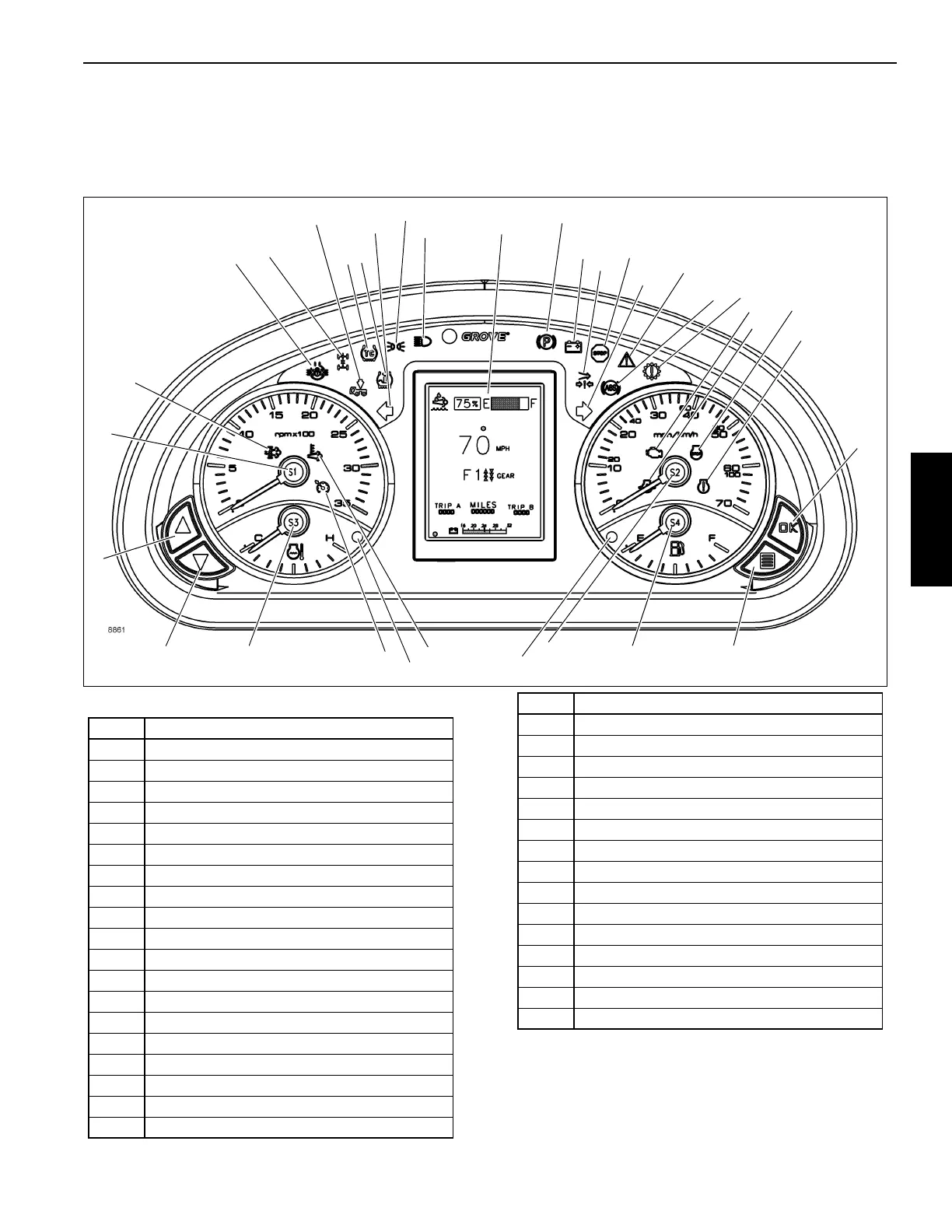
CONTROL PANEL INDICATOR AND GAUGE
DISPLAY
As a system check, the indicators will come on for two seconds when the ignition switch is turned to the RUN position.
(Figure 3-5) Item Numbers
Cross-Axle Locked Indicator
The Cross-Axle Locked indicator (1)((Figure 3-5)) is located
at the left side of the gauge cluster. The indicator illuminates
amber to show that the differential is locked.
32
31
30
1
2
3
34
6
5
4
10
9
8
17
16
15
20
11
21
22
23
29
28
FIGURE 3-5
7
12
13
14
18
19
24
25
26
33
27
Item Description
1
Differential Locked
2 Inter-axle Locked
3 Suspension Deflated
4 Traction Control
5 Tire Inflation
6 Left Turn Signal
7 Lights On
8 High Beam
9 Park Brake Engaged
10 Battery Charge
11
Low Air Pressure
12
Emergency Stop
13 Right Turn Signal
14 System Fault Indicator
15 Anti-lock Braking System
16 Check Transmission
17 Malfunction Indicator Lamp
18 Low Oil Pressure
19 Engine Stop
20 Engine Warning
21 OK Button
22 Menu Button
23 Fuel Gauge
24 Speedometer
25 Low Fuel Level Indicator
26 High Exhaust System Temperature
27 High Water Temperature Indicator
28 Cruise Control
29 Engine Coolant Temperature Gauge
30 Down Button
31 Up Button
32 Tachometer
33 Exhaust System Cleaning Needed
34 LCD Display
Item Description

 Loading...


