SET-UP AND INSTALLATION TMS9000-2 OPERATOR MANUAL
6-72
Published 02-21-2019, Control # 611-05
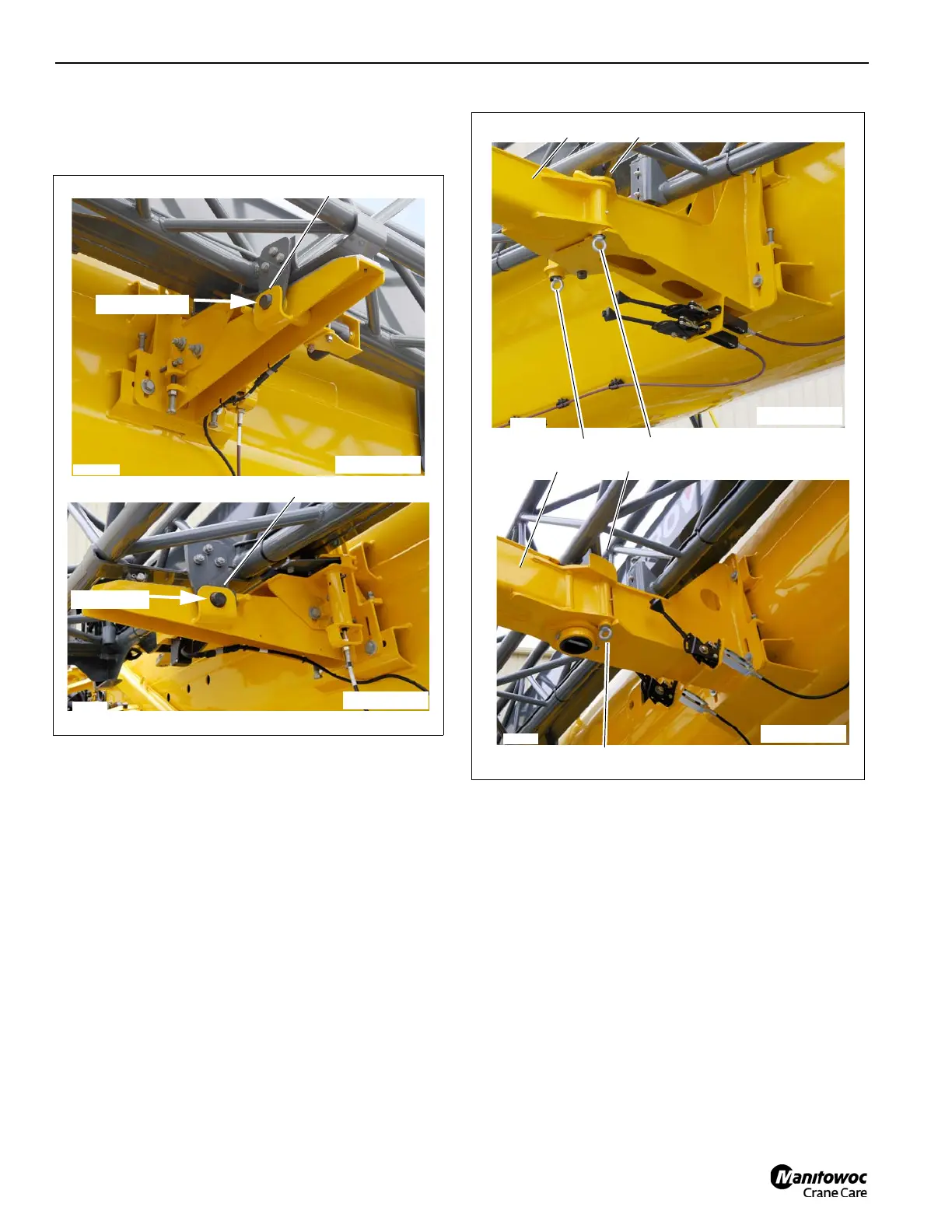
13. Verify the pins (1 and 2) (Figure 6-140) are engaged with
the lugs.
14. Verify pin #1 (1) (Figure 6-141) is engaged.
15. Pull the locking pin (1) (Figure 6-142) down against
spring force, and out of the attachment lug (2). Fold the
run-up ramp (3) around until it can be secured with the
spring latch (4) Design A. Pull the locking pin (1)
(Figure 6-142) down against spring force, and out of the
attachment lug (2). Fold the run-up ramp (3) around until
it can be secured with the spring latch (1) Design B
16. Remove all tag lines.
17. Reeve the hoist cable over the main or aux boom nose
as preferred.
Boom Extension Removal
Removal of the boom extension can be done in two ways:
From the side of the main boom and from the nose of the
main boom.
FIGURE 6-141
8969-35
1
9728-5
Design B
Design A
1
Engaged
Engaged
FIGURE 6-142
8969-4
1
Design B
9728-9
1
Design A
2
3
4
2
3

 Loading...


