SET-UP AND INSTALLATION TMS9000-2 OPERATOR MANUAL
6-56
Published 02-21-2019, Control # 611-05
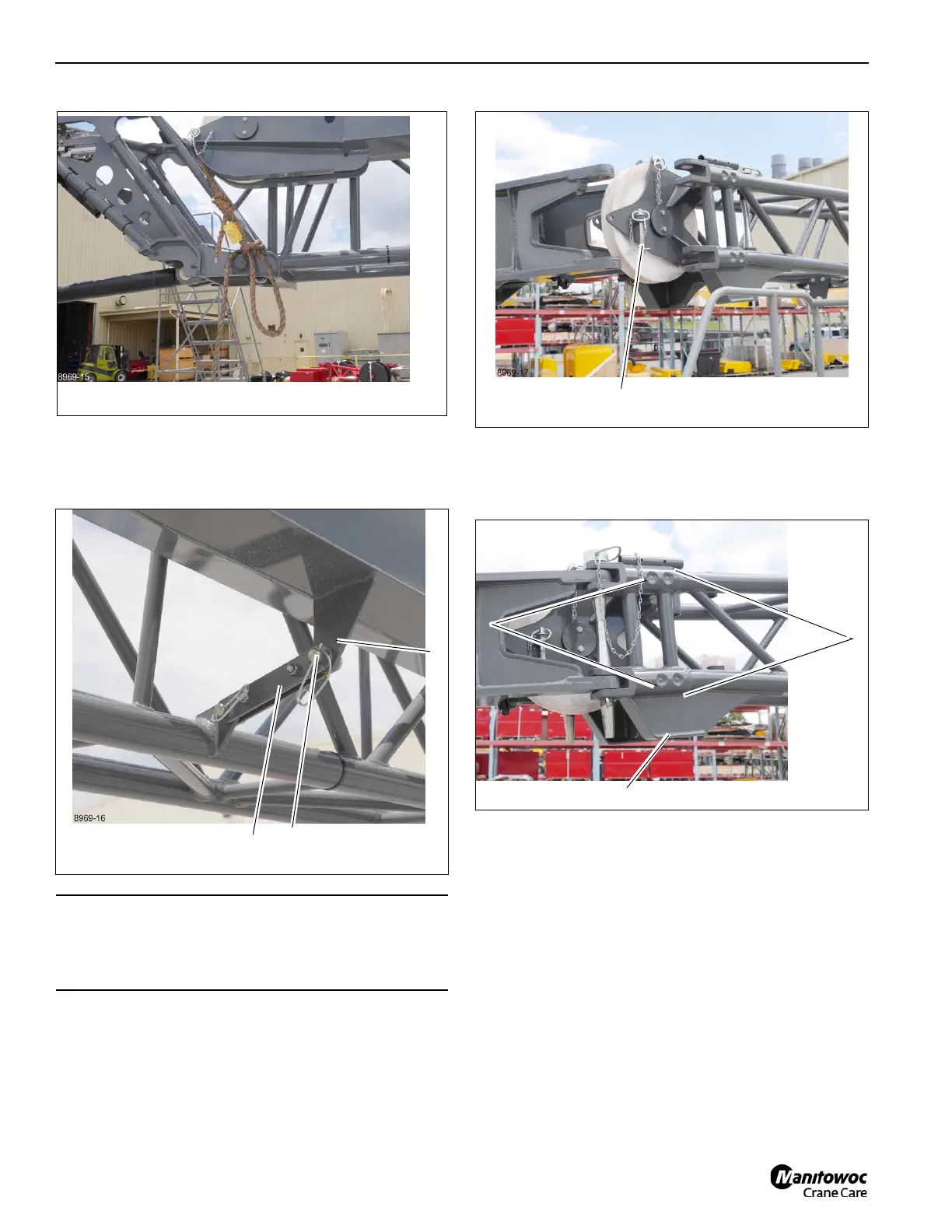
18. Remove the retaining clip from pin (1, Figure 6-107) and
remove the pin from the locking bar (2) and the fly
extension (3). Insert the pin in the locking bar and secure
with the retaining clip.
19. Using the tag line swing the fly extension around and
engage the fly attachment fittings (1, Figure 6-109) with
the base extension anchor fittings (2). Install the pin (3)
into the fittings and secure with a retaining clip.
20. Establish electrical connections between the base
extension and the main boom, refer to 58 ft (17.7 m)
Extension Electrical Connections, page 6-57.
21. Install the anti-two block switch, refer to 58 ft (17.7 m)
Extension Anti-Two Block Installation, page 6-58
Extension Electrical Connections
To connect the anti-two block switch, boom position indicator
light or anemometer to boom extensions the following
procedures must be performed.
35 ft (10.5 m) Extension Electrical Connections
The following procedure connects the 35 ft base extension
wiring to the main boom circuits. This connection must be
CAUTION
Equipment Damage!
If the cable retainer pin is not removed it will come into
contact with the fly extension causing damage.

 Loading...


