EasyManuals Logo
Home>Manitowoc>Construction Equipment>Grove TMS9000-2 Series

Manitowoc Grove TMS9000-2 Series User Manual

Manitowoc Grove TMS9000-2 Series
430 pages
To Next Page IconTo Next Page
To Previous Page IconTo Previous Page
Page #387 background imageLoading...
Page #387 background image
GROVE 6-51
TMS9000-2 OPERATOR MANUAL SET-UP AND INSTALLATION
6
Published 02-21-2019, Control # 611-05
5. Push the Design A horizontal actuated hand levers (3,
Figure 6-93) towards the rear of the main boom. Push
the Design B vertical actuated hand levers fully
downwards. This disengages the pins that secure the fly
extension to the main boom (1, Figure 6-94).
FIGURE 6-92
8969-3
1
2
2
Design A
Design B
1
2
9728-9
DANGER
Boom Extension Hazard!
Ensure the fly extension is secured to the main boom
before removing connections to base extension. Failure
to do so could result in death or serious injury.
FIGURE 6-93
8969-4
1
2
3
Design B
9728-9
2
3
1
Design A

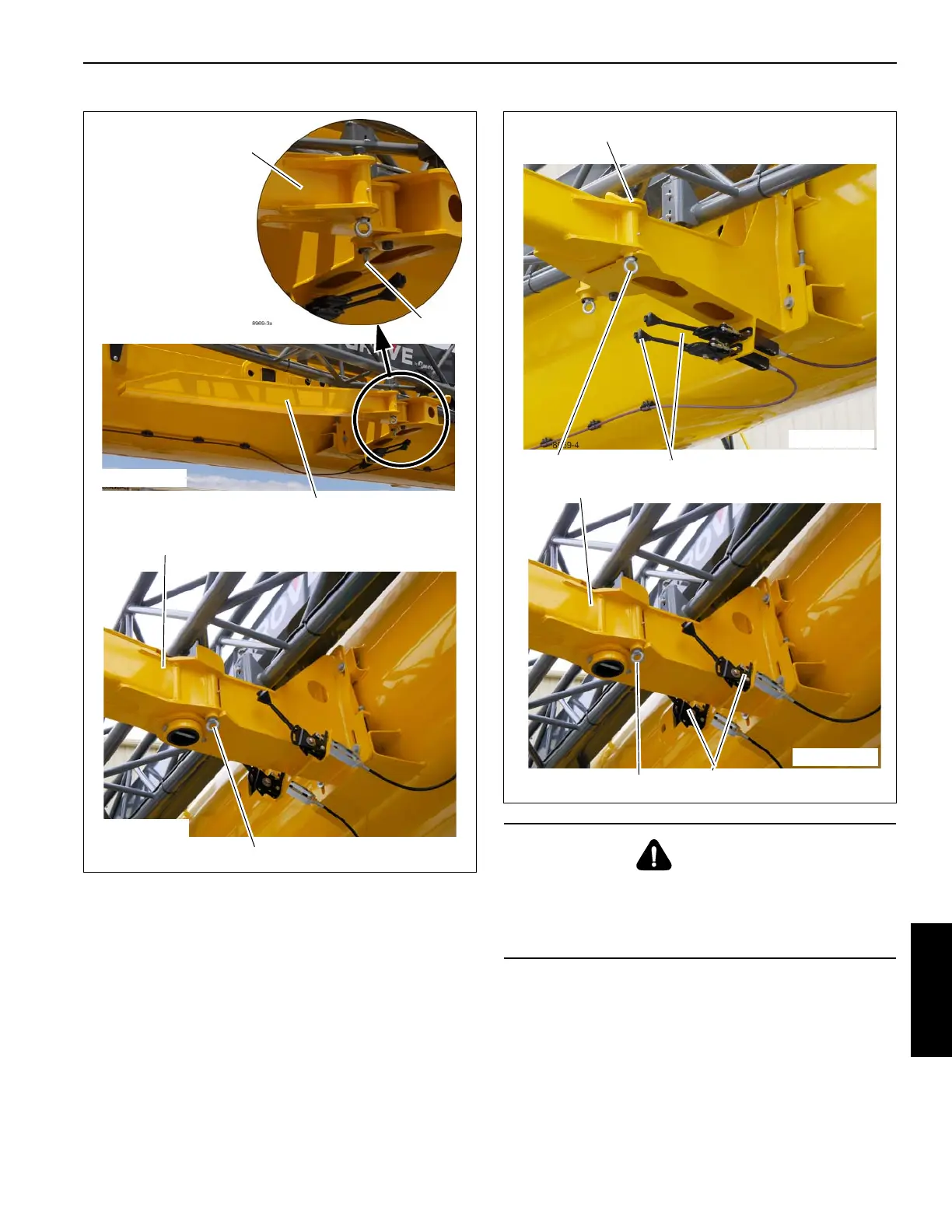
Table of Contents

Questions and Answers:

Question and Answer IconNeed help?

Do you have a question about the Manitowoc Grove TMS9000-2 Series and is the answer not in the manual?

Manitowoc Grove TMS9000-2 Series Specifications

General IconGeneral
BrandManitowoc
ModelGrove TMS9000-2 Series
CategoryConstruction Equipment
LanguageEnglish

Related product manuals