Structure and Assembly/Disassembly 9-7
9.3.4 IO BOX Board and WIFI PCBA
1. Remove the rear cover. Refer to procedure 1 and 2 in 9.3.3.
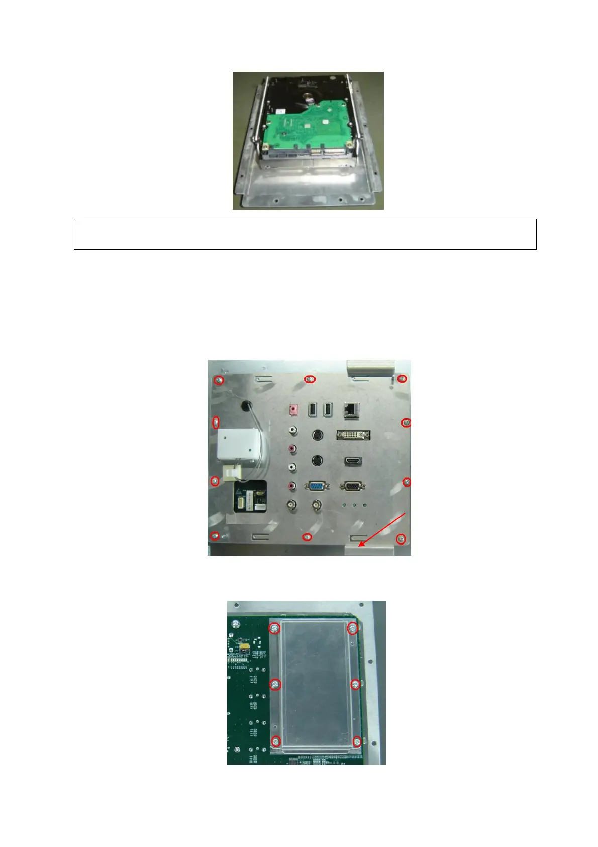
2. Remove ten M3X8 screws and hold the two supporting lugs to pull out the IO BOX board
module.
3. Unscrew the M3X8 screws (6 pcs) securing the WIFI PCB shielding cover, and then remove
the cover.
The length of hard disk data wire is limited, please pay attention when take it out to
prevent from damaging the linker of hard disk.

 Loading...


