Product Principle 4-15
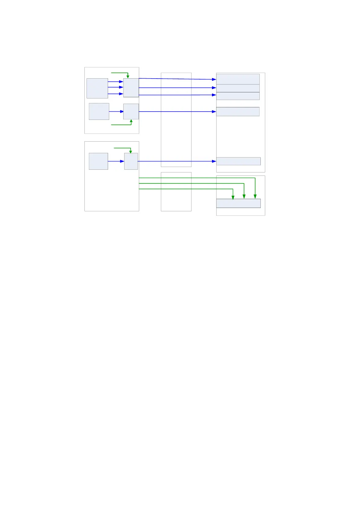
4.3.7 Indicators on the Ultrasound System
Control panel
Back-end power board
Power-on status
indicator
Power
managem
ent
Drive
Battery
manage
ment
Drive
Back-end
motherboard
Digital board
CPU
module
Drive
5VSTB
5VSTB
3.3V
Standby status
indicator
Battery status indicator
HDD indicator
AC power status
indicator
Front-end
motherboard
IO BOX board
Power status indicators
12V
5V
3.3V
Fig 4-18 Block Diagram of Indicators on the Ultrasound System
4.4 Control Panel Unit
The control panel unit mainly consists of keyboard module.
The keyboard module consists of on/off key, retractable keyboard, trackball, TGC slider, and
encoder, including key volume and key light. The key, trackball, TGC and encoder are used for
signal input, key volume and key light for output.
USB HUB is adopted for USB extending on the keyboard. See the figure below, the following
function circuits are designed on the control panel.
On/off key circuit;
TGC adjust circuit;
Trackball circuit;
LED drive control circuit;
Key volume circuit;
FPGA control circuit;
Encoder circuit;
USB HUB circuit.

 Loading...


