10-4 Optional Installation/Assembly
Gel warmer
material
package (with
power
adapter
cable)
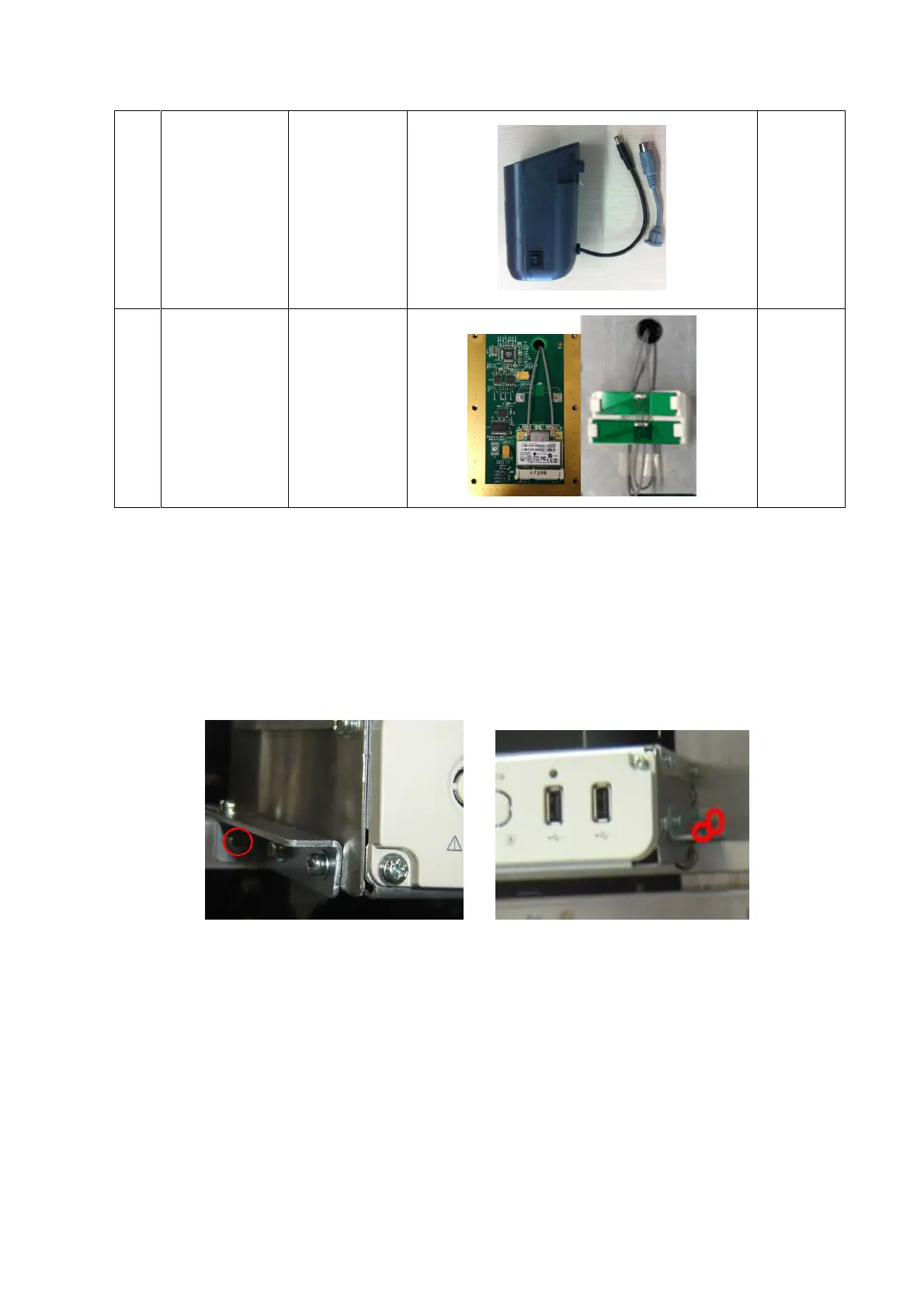
10.2.1 Front Board USB&ECG and Pencil Probe Port
Assembly
1. Remove the front cover. Refer to procedure 1 to 5 in 9.3.2.
2. Unscrew three M4x8 screws and hold front board USB assembly and then pull it out.
3. Confirm the connection between back-end motherboard and ECG signal wire is ok. The front
board USB, ECG and pencil probe ports assembly is connected to the socket of ECG signal
wire (former position of the front board USB assembly) and then fixed it to the main unit racket
by three M3X8 screws.

 Loading...


