Product Principle 4-3
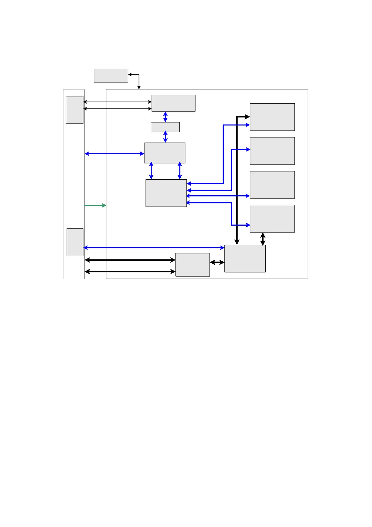
4.2.1 Probe Board
Front-
end
analog
mother
board
Probe socket D
Probe socket C
Probe socket B
Probe socket A
Signal switch
( relay unit )
…
CPLD
Probe related control
signal
Pencil probe socket
245 drive
4D&
TEE
signal
socket
CW transmitting & receiving signal
CW_POUT
4D&TEE signal
Transmitting & receiving signal
Probe control
circuit
…
Probe control signal
A+12V/A+5V7/A+100
V/A-100V
Pencil probe/probe present signal
Signal switch
( relay unit )
Transmitting& receiving
signal POUT
Pencil
probe
signal
socket
Pencil probe
socket
Probe board
Fig 4-3 Schematic diagram of probe board
Hardware structure of the probe board is shown as the figure above:
Functions of the probe board are:
Supports 256/192/128elements probes, 4D probes, 128/96/64-elements phased array probes
and TEE probes;
Probe board only supports 128 channels; for 192/256elements probe, elements switching is
performed in the probe to match 128 channels on board. Including four 260-pin probe sockets.
Supports 4 probe ports switching and ID recognition of probes on every port. The circuits for
ID recognition and probe switching are independent.
Supports echo signal channel switching, outputting CW signal independently which can
improve CW signal-noise ratio.

 Loading...


