Product Principle 4-21
4.8.3 Back-end Power Board
STANDBY
DC-DC
D+5V&D+
3.3V
DC-DC
D-12V
DC-DC
D-5V
DC-DC
FPGA
Power status
Power control
MCU
BATTERY
CHARGE
Charge enable
3V3STB_FPGA
3V3STB_MCU
D+12VSTB
EDC_+12V
Auxiliary output control
Temperature collection
BATT+
Battery temperature
Battery status and
communication
System On/off
status indicating
signal
D+5V
D+3.3V
D-12V
D-5V
D+5VSTB
Back-end power board
Power
management
Battery management
Power module
Back-end motherboard
D+12VSTB
Battery
assembly
Select
circuit
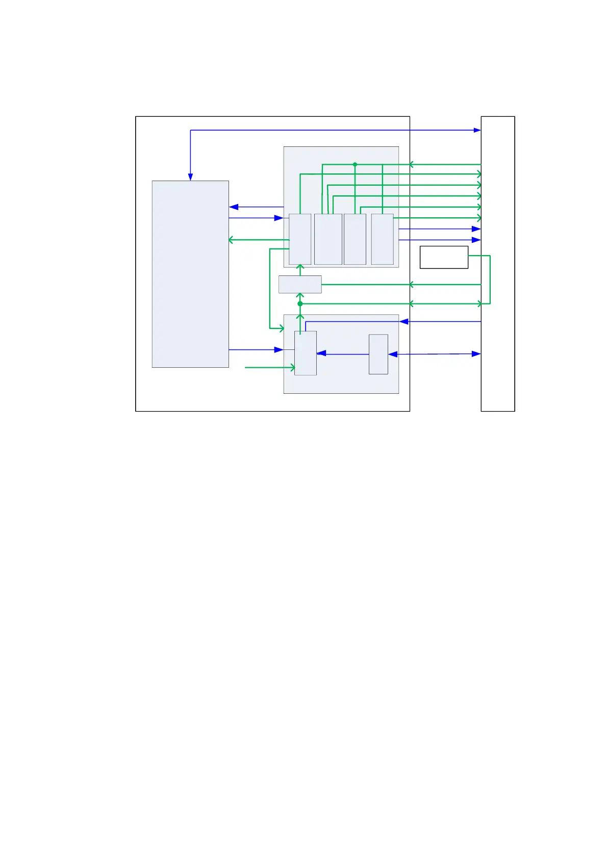
Fig 4-26 Schematic Diagram of the Back-end Power Board
Function description:
Back-end power board mainly consists of power management, battery management and
DC-DC power module. When the D+12VSTB of pre-level AC-DC power starts working, the
corresponding power management and batter management part begin to work, the system
enters into Standby mode, and the battery charge (supplied by D+12VSTB) circuit begins
to work.
The back-end power board, according to the CPU module status information and the
FPGA and battery current information. After the system is turned on, the powers except
Standby will output normally, to power the back-end boards. When system is in boot-trap
status, the power charge circuit still works normally.
When the machine is configured with battery, the machine can enter into standby mode
when it is powered on by mains power. And when the mains power is cut off, the battery
will power the system to make the system maintain in standby mode, until the battery is of
low capacity or the mains power is connected again. The battery only supports Standby
mode. And in this mode, the mains power is prior to the battery.
4.8.4 Front-end Power Board
The front-end power board consists of front-end power main board and front-end power auxiliary board.
See the figure below, the external ports of the front-end power board are realized by the front-end power
main board, the front-end power auxiliary board is connected with the front-end power main board, but
not connected with the other boards. The EDC_+12V is connected to the front-end power main board
through the back-end motherboard, meanwhile it is connected to the front-end power auxiliary
board to power the two boards. They are introduced respectively as follows:

 Loading...


