4-2 Product Principle
Power supply unit (front-end power board, back -end power board, AC/DC power board).
4.2 Ultrasound Front-end Unit
Front-end analog motherboard
Transmission
board B
High
voltage
isolation
TGC
CW board
Beamformer
FPGA 1
DSP
FPGA
PCIE
Receiving board
ADC VGA LNA
Clock
circuit
Probe board
64-channel transmissionCommunication control bus
Communication
control bus
Communication
motherboard
128-channel analog
Analog transmission&receiving
Digital echo
Clock 3
Clock 1
Clock 4
Clock 6
Control signal
Transmission
board A
64-channel transmission
Communication control bus
Clock 2
Beamformer
FPGA 2
Beamformer data
Signal processing board
Communication
control bus
Clock 5
High
voltage
isolation
ADC VGA LNA
Clock 7
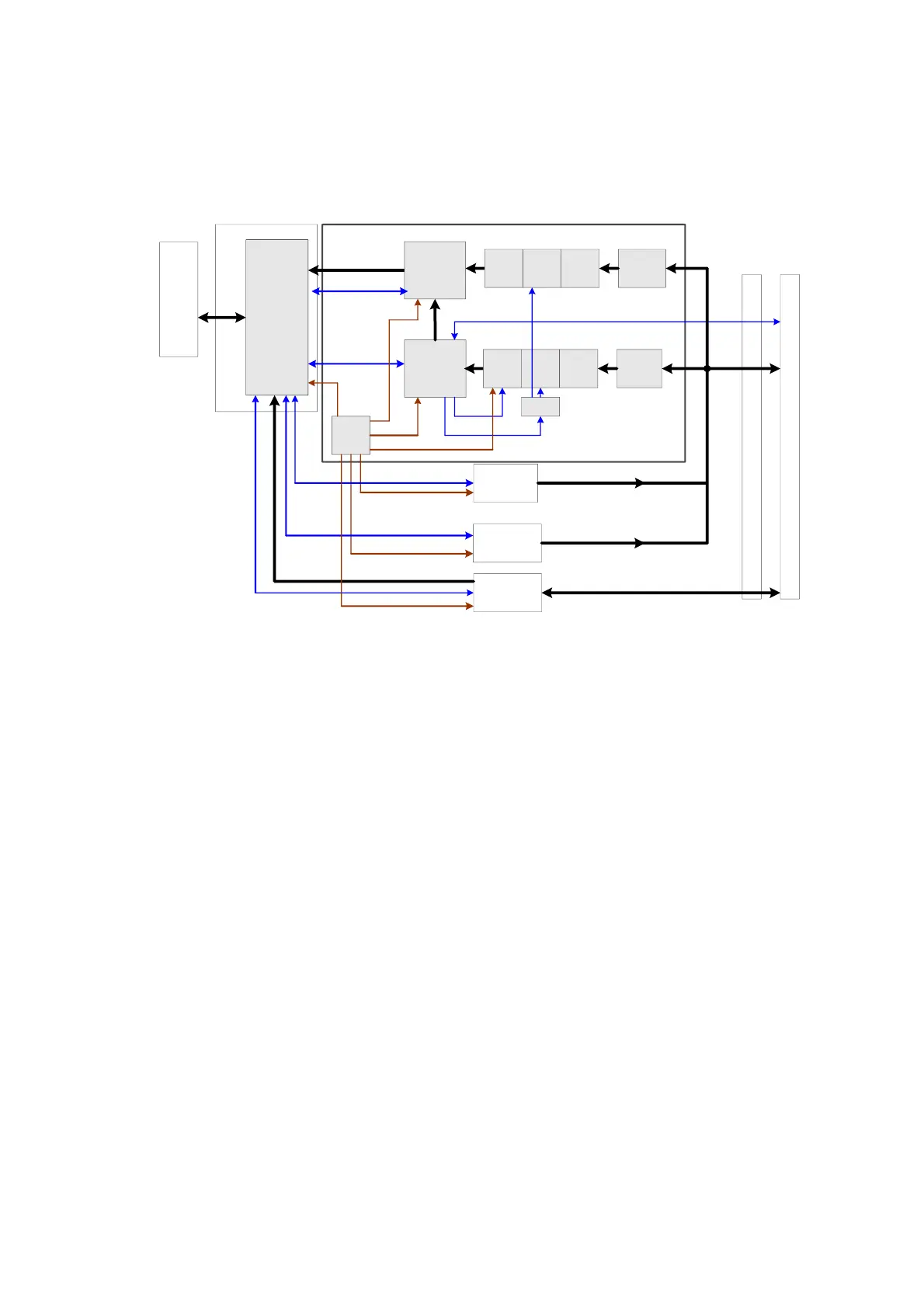
Fig 4-2 Schematic diagram of ultrasound front-end unit
Front-end unit mainly consists of:
Probe board
CW board;
Transmission board A and transmission board B;
Receiving board
DSP board (Signal processing board for short ,supporting 4D and elastography);
To separate the analog area from the digital area properly, front-end analog motherboard (mainly
contains front-end analog signal channel) and communication motherboard (mainly contains digital
signal and power channel) are added to the system. Front-end receiving unit carries out
128-channel transmitting and receiving. The ultrasound image signal will be sent to the CPU
module on the digital board for post processing after amplification, A/D conversion, beam forming
and signal processing.
For details of the boards, see the following chapters:

 Loading...


