10-12 Optional Installation/Assembly
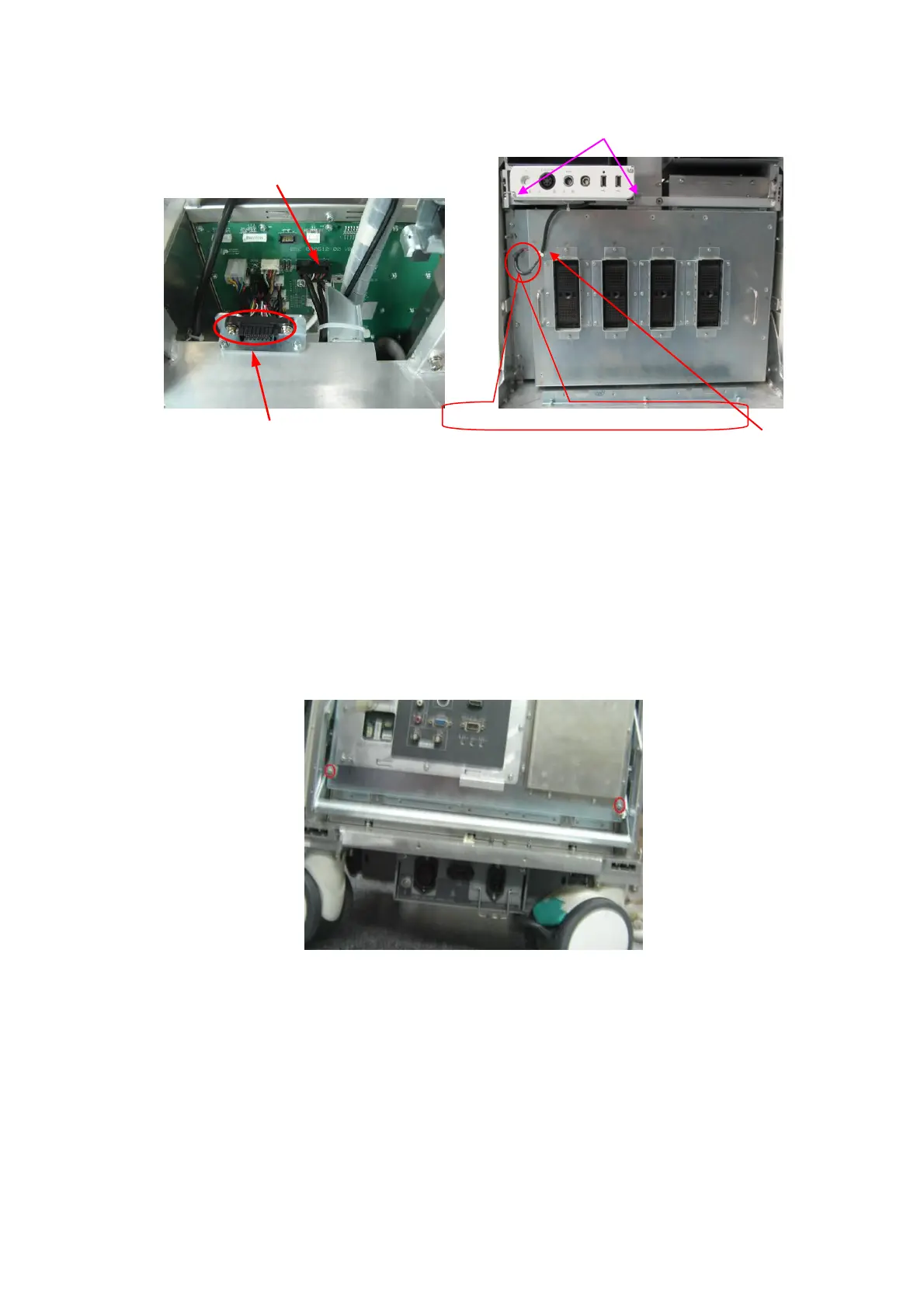
3 pcs of M4X8 Philips pan headed screws, 1 left, and 2 right
Pencil probe cable and one cable tie
10. Refer to procedure 1 to remove front cover of the main unit and then reversely assemble the
cover, printer cover and storage box cover. Assembly is finished.
10.2.2 4D Module
10.2.2.1 4D or 4D&TEE board and Signal Processing Board (supporting
4D/elastography)
1. Remove the rear cover. Refer to procedure 1 and 2 in 9.3.3.
2. Unscrew two M3X8 screws securing the handle.
3. Unscrew 26 M3X8 screws fixing Communication Mother Board Assembly.

 Loading...


