13-4 Troubleshooting of Regular Malfunctions
Imaging characteristics of all models of probes
when connecting on the same or different ports
There may be some relay switching is
damaged when replacing the transducer
or the array of the transducer
Main Voltage Test in self-test
ATGC Function Test in self-test
AFE Noise Test in self-test
AFE Digital Interface Test in self-test
Digital Board and DSP Board
Interconnection test in self-test
DSP Board and Transmission Board
Interconnection test in self-test
DSP Board and Receiving Board
Interconnection test in self-test
Interconnection test in self-test
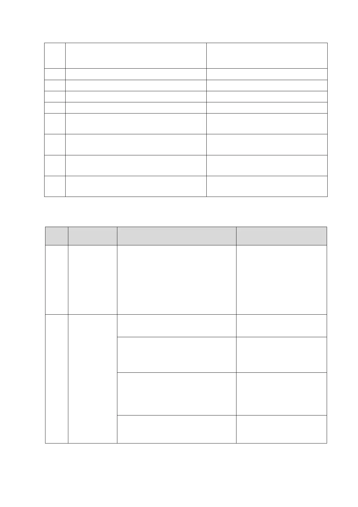
13.3.3 Troubleshooting for Image Displaying
No image echo
in the ultrasonic
image region,
but probe can
be recognized.
PHV voltage output is 0V or abnormal;
Malfunction on the transmission board,
front-end power main board or probe
board.
Malfunction probability on the
transmission board is bigger
than that of front-end power
main board PCBA. The third is
probe board. Replace
transmission board, front-end
power main board or probe
board to confirm the
malfunction.
Probe malfunction, e.g. array damage.
Confirm it by connecting another probe.
If dark strips appear in the near field.
only one strip or distribute regularly
May be some transmission channels
can’t generate transmission waveforms.
Replace the transmission
Board
If dark strips appear in the far field. only
one strip or distribute equivalently;
There may be failure on the receiving
channels, for example, some channel
cannot receive or generate echo signals.
Replace the receiving board.
If dark strips appears casually for one
probe with different sockets
Malfunction may be on probe board.
Replace the probe board
assembly.

 Loading...


