NV8500 family Digital Routers • User’s Guide 93
2. Installation
Verification
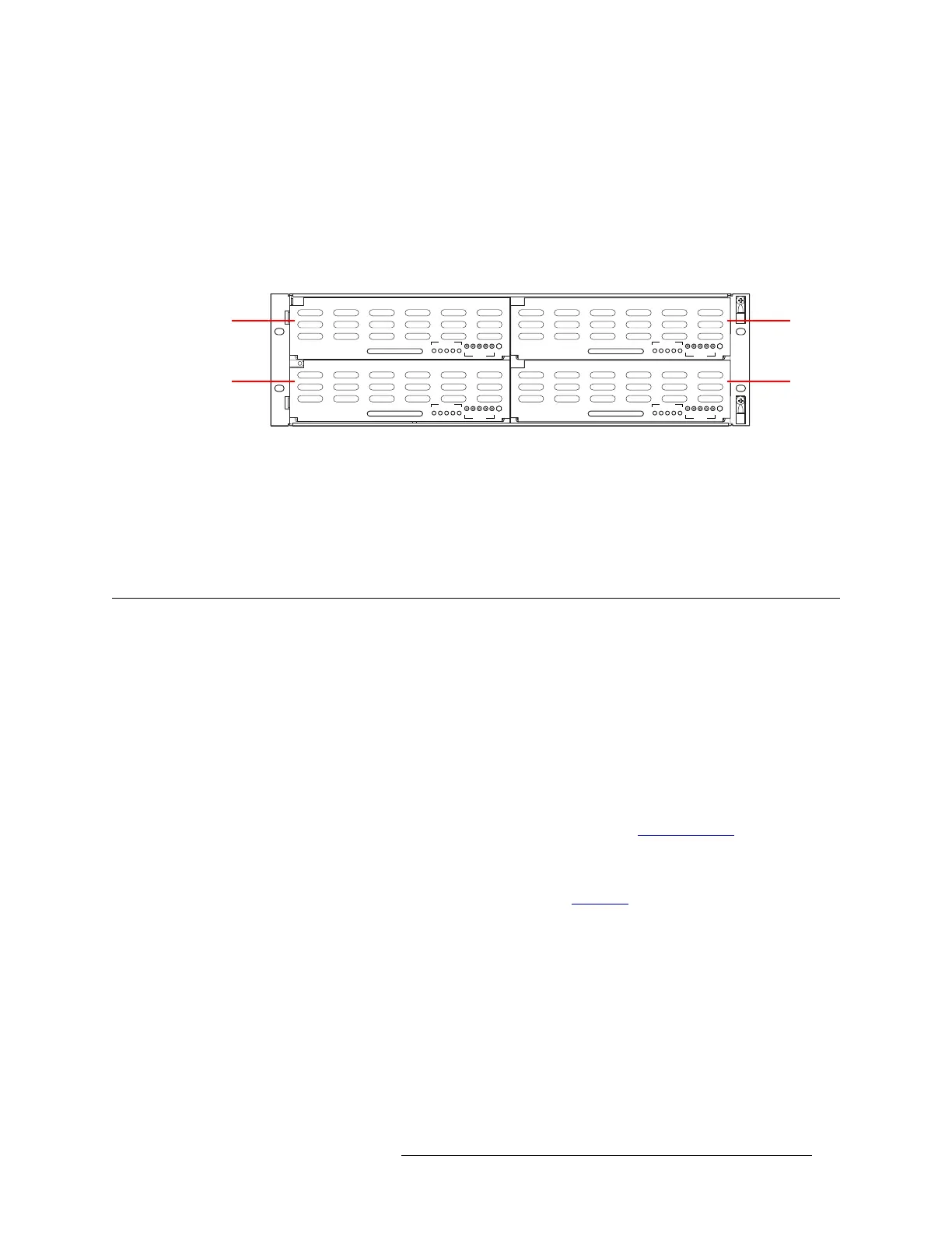
9 Install the PS8100 power supply modules as follows:
a At the front of the NV8000, install primary PS8100 power supply modules in slots 1 and 3,
as shown in Figure 2-39.
b Optionally, install redundant PS8100 power supply modules in slots 2 and 4, as shown in
Figure 2-39.
c Repeat this step for the other power supply.
Figure 2-39. NV8000 Power Supply (Front View)
10 Connect the router’s ground lug to earth ground using a copper wire from 14 to 6 AWG. The
ground lug is located in the lower right corner of the frame.
11 If you have two NV8280-Plus or NV8576-Plus frames, connect power similarly for both
frames. Four NV8000 frames are required to power two NV8280-Plus or NV8576-Plus frames.
Verification
When installation is complete, perform the following checks to make sure the router is operating
properly:
• If using an NV8000 power supply frame, check that all 5 green power LEDs on the front of
each PS8100 power supply module are lit. If any or all LEDs are off:
• Check that the PS8100 power supply module is fully seated in its slot.
• Check for +48 volts at each of the 5 front test points.
• On the router frame, check that the LEDs on the input cards, crosspoint cards, control cards,
and output cards are lit and indicating a “healthy” system. See Indicator LEDs
on page 101 for
a list of normal and alert LED states.
• Make sure that the flow of air through the front of the router is unimpeded and the door is prop-
erly installed and closed. For more information, see Air Flow
on page 103.
GND
PS8010
12345
12345
POWER
48V
+
GND
PS8010
12345
12345
POWER
48V
+
GND
PS8010
12345
12345
POWER
48V
+
GND
PS8010
12345
12345
POWER
48V
+
1 (primary) 2 (redundant)
4 (redundant)3 (primary)
 Loading...