26 Rev 2.2 • 27 Mar 10
1. Introduction
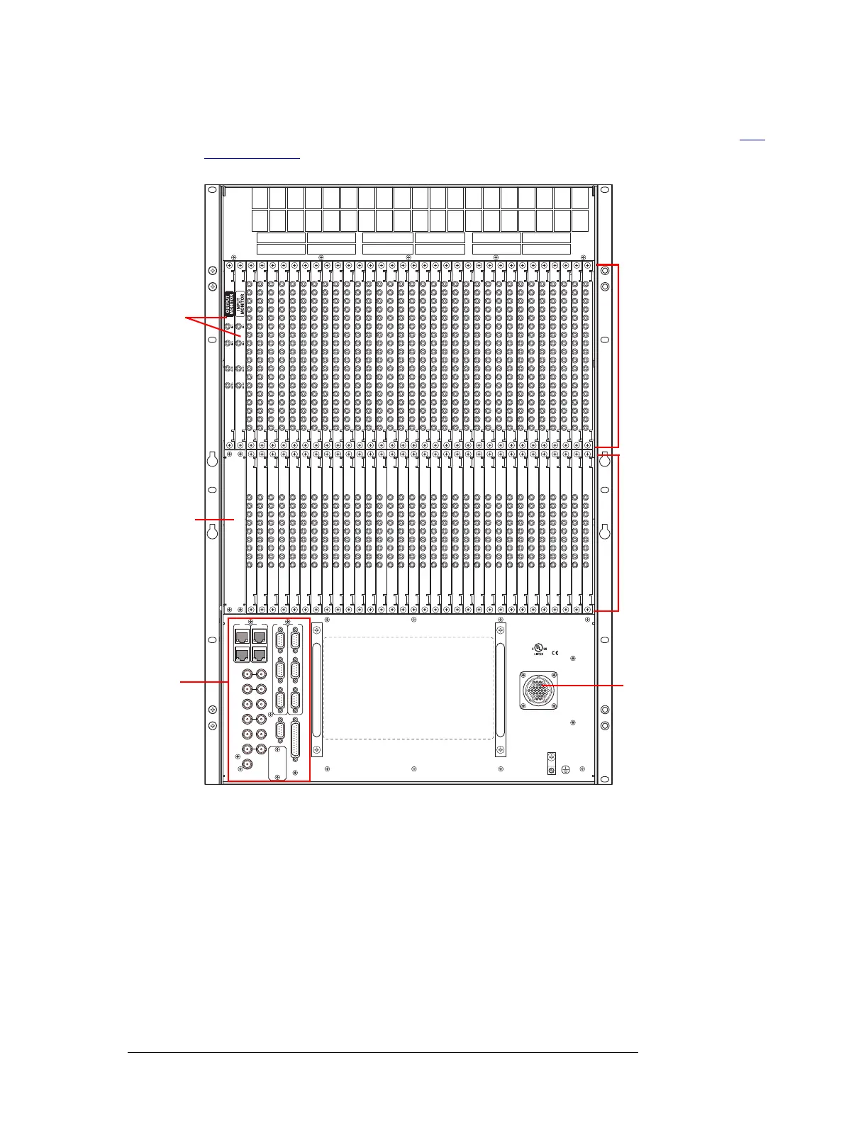
Front Module Slots and Rear Connections
Near the bottom of the frame are connections for system and power functions. For details, see Sys-
tem Connections on page 32.
Figure 1-20. NV8280/NV8280-Plus Rear of Router Frame (Rear View)
NV8576 and NV8576-Plus
Similar to the front of the router, the rear of the frame is divided into three general regions: upper,
middle and lower. The upper and lower regions are mirror images of each other featuring a total of
32 slots for output backplanes corresponding to output cards and 32 slots for input backplanes cor-
responding to input cards, for a total of 64 backplanes for outputs and 64 backplanes for inputs. The
input backplanes can contain either 9 DIN 1.0/2.3, terminal block, or LC connectors, through which
incoming signals are received. The output backplanes can one of two sets of connectors: 18 DIN
1.0/2.3, terminal block, or LC connectors that distribute outgoing signals or if for expansion 9 DIN
1.0/2.3, terminal block, or LC connectors that distribute outgoing signals plus 2 high-density con-
10/100 BT
RTR EXP
10/100 BT
RTR EXP
VIDEO REF 1
PRI
SEC
CONTROL
CTRL 1
CTRL 2
CTRL 1
CTRL 2
DIAG (38.4 Kbaud)
DIAG (38.4 Kbaud)
VIDEO REF 2
AES REF 1
AES REF 2
RTR EXP IN
ALARMS
RTR EXP OUT
NVISION AUX BUS
POWER
SUPPLY
MONITORS
TIME CODE
E146905
POWER INPUT
PRI
SEC
Fan
Output
Backplanes
(32)
Input
(32)
Backplanes
Backplate
for Control
Card slots
System
Connections
Connection
Power
Monitor
Backplanes
(2)
 Loading...