NV8500 family Digital Routers • User’s Guide 53
2. Installation
Installing Cards
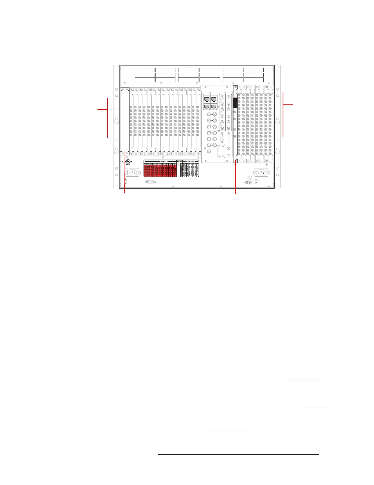
Figure 2-3, shows the backplane locations at the rear of an NV8144 router.
Figure 2-3. NV8144 Frame with Backplanes (Rear View)
How to Install a Backplane
1 Facing the rear of the router, locate the slot into which a backplane is to be installed. If you are
reconfiguring the router, relocate backplanes as needed.
2 Insert the new backplane into the frame being sure to align the printed circuit board with the
stamped guides in the frame. Use gentle pressure at the top of the backplane to ensure the back-
plane connector is fully mated with the motherboard.
3 Tighten the two spring-loaded backplane retention screws.
4 To maintain proper airflow for cooling, all backplane slots must have a backplane or cover plate
installed.
Installing Cards
Routers in the NV8500 family use a number of active cards that manage incoming signals, forward-
ing of control system commands, signal switching, and distribution of outgoing signals. Cards slide
into a card guide in such a way that the connectors on the rear of the card interface with the mother-
board. Each card is color-coded with an ejector lever that matches the color of the card guide into
which the card is installed in the router frame. For a description of each card, see Active Cards
on
page 37.
For each card installed, a corresponding backplane must also be installed. The backplane contains
the connectors that connect to cabling for the receiving and distribution of signals. (See Backplanes
on page 29.) As you install cards, check the corresponding backplane. If the red LED on the back-
plane lights, the card and backplane do not match. If the green LED on the backplane lights, the
card and backplane are a correcting pairing. (See Indicator LEDs
on page 101.)
DIAG (38.4 Kbaud)
CONTROL
IN 1
MONITOR
OUTPUT
IN 2
OUT 2OUT 1
POWER
SUPPLY
i
MONITORS
TIME CODE
NVISION AUX BUS
RTR EXP OUT
RTR EXP IN
AES REF 1
AES REF 2
VIDEO REF 2
VIDEO REF 1
RTR EXP
10/100 BT
RTR EXP
10/100 BT
CTRL 1
CTRL 2
ALARMS
CTRL 1
CTRL 2
DIAG (38.4 Kbaud)
PRI
SEC
SEC
PRI
90-130V~/180-250V~
12.5A/6.25A
50/60Hz
1125 WATT S MAX
PS1
PS2
90-130V~/180-250V~
12.5A/6.25A
50/60Hz
1125 WATT S MAX
E146905
CNTRL NO. 9K50
PROFESSIONAL
VIDEO/AUDIO
ALARMS
Monitor Backplane (1)
Control card area
(no backplanes)
Output
Backplanes (8)
Input
Backplanes (16)
 Loading...