34 Rev 2.2 • 27 Mar 10
1. Introduction
Front Module Slots and Rear Connections
For the router to communicate with the router control system through an Ethernet connection, you
must configure an IP address in the control card. The IP address is set using UniConfig. However,
UniConfig runs on a PC and similarly cannot communicate with the router until an IP address has
been entered. Therefore, you must use a serial connection
— using the ‘DIAG’ port(s) — to the
computer (PC) running UniConfig to define the IP address(es). (See Serial Control Connections
on
page 70.)
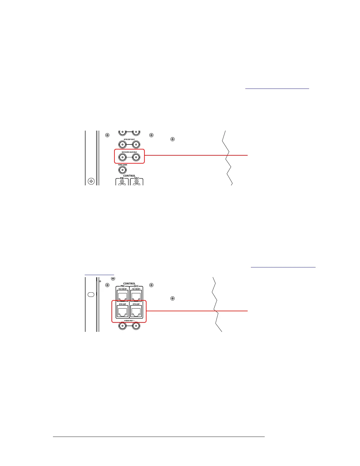
Aux Bus Control Connections
The Miranda Aux Bus connection is located on the rear of the router. However, the Aux Bus con-
nection is not used at this time.
Figure 1-26. AUX Bus Control Connections (Rear View)
Control System Expansion Connections
In order to manage two connected expandable router frames (NV8280-Plus or NV8576-Plus), con-
trol system expansion connections need to be connected between the routers. Expansion control
system connections are located on the rear of the router, as shown in Figure 1-27.
There are two connections provided. Only one is required for control system expansion connec-
tions. The other connection is available as a redundant connection, providing a backup connection
to the control system should the other connection fail.
For instructions on making control system expansion connections, see Control System Expansion
Connections on page 73.
Figure 1-27. Expansion Control System Connections (Rear View)
Diagnostic Connections
The diagnostic connections enable the router to communicate with the UniConfig application. Uni-
Config runs on a PC separate from the router and is used to perform system setup tasks, and config-
ure and monitor the router. Please refer to the UniConfig User’s Guide.
Diagnostic connections connect the router to the computer (PC) running the UniConfig application.
Two diagnostic connections are located on the rear of the router, labeled ‘DIAG’. The ports are
divided into two sets: one primary (‘PRI’) and one secondary (‘SEC’), as shown in Figure 1-28.
The primary control connects to the primary control card. The secondary control connects to the
GSC Node Bus
Connectors
Expansion Connectors
 Loading...