64 Rev 2.2 • 27 Mar 10
2. Installation
Making Signal Connections
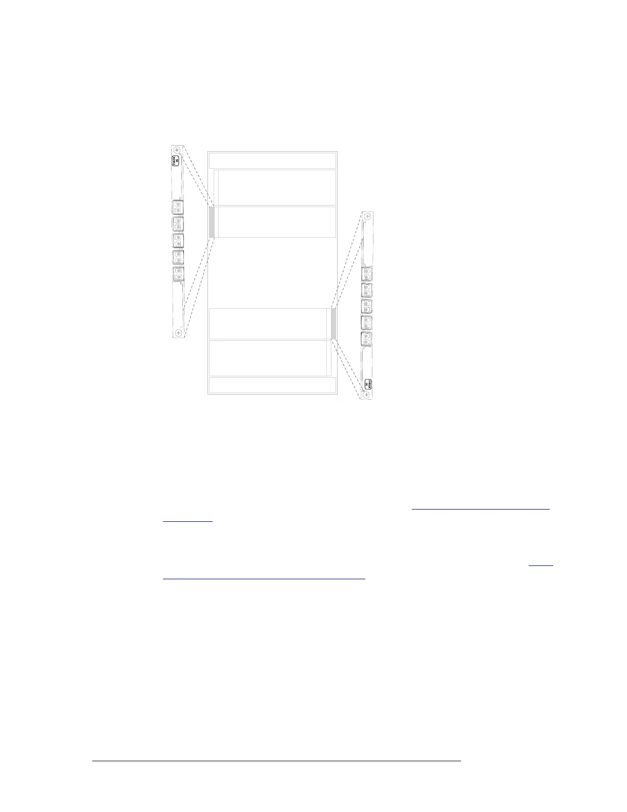
ing at the bottom and connecting to each connector in turn, leaving the remaining top connector
empty. See Figure 2-11.
Figure 2-11. NV8576 LC Input Backplanes (Rear View)
3 Connect the other end of the cable to the source of the incoming signal.
4 Locate the output connections on the rear of the router.
Backplanes in the standalone router frames (NV8144, NV8280, NV8576) contain 18 connec-
tors each.
Backplanes in the expansion router frames (NV8280-Plus, NV8576-Plus) contain 9 connectors
each plus two additional connectors used for expansion. See “
Expansion Signal Connections”
on this page.
5 For each output, connect to an output connector using a DIN 1.0/2.3 connector and 1855A
Belden cable, or an equivalent, or a LC connector and fiber optic cable, or a WECO connector
and coax cable. For details on the signal number assigned to an individual connector, see Back-
plane Connectors and Individual Signal Numbers on page 14.
6 Connect the other end of the cable to the distribution destination for the outgoing signal.
7 For expansion router frames being connected to a second router, make signal expansion con-
nections. (See Expansion Signal Connections following.)
Expansion Signal Connections
Using expansion signal connectors, two routers can send signals between connected router frames
creating a matrix of up to 576 x 576 (NV8280-Plus) or 1152 inputs and 1152 outputs (NV8576-
Plus). The expansion connections use expansion cables (WC0121) available from Miranda. Con-
nected routers must be situated physically near each other, side by side.
Inputs
Outputs
Inputs
Outputs
Input Backplanes
1
2
3
4
5
7
8
9
6
Not
used
1
2
3
4
5
7
8
9
6
Not
used
 Loading...