32 Rev 2.2 • 27 Mar 10
1. Introduction
Front Module Slots and Rear Connections
System Connections
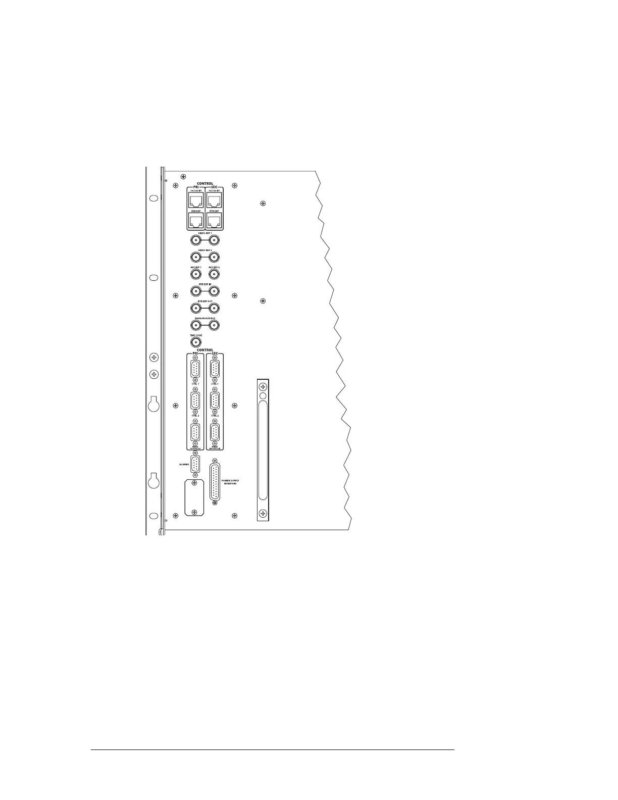
Routers in the NV8500 family feature connections for managing system functions, located on the
rear of the router, as shown in Figure 1-23. The following is an example of an NV8576 router
frame. While the system connections may not be positioned exactly as shown in this example, all
connections are labeled as indicated and perform the functions stated in the following sections.
Figure 1-23. System Connections for NV8576 Router Frame
These connections allow you to connect:
• A router control system.
• Reference signals.
• A PC running the UniConfig application.
• System alarms that sends notification of a system failure, such as a fan or power supply mal-
function.
Router Control System Connections
Router control systems run on a separate platform connected to the router. The router provides two
ways to connect to a router control system: serial or Ethernet. There is also an Miranda Aux Bus
connection present, but it is not being used at this time. The router control system determines which
 Loading...