NV8500 family Digital Routers • User’s Guide 75
2. Installation
Making AES Reference Connections
How to Make Permanent Diagnostic Connections
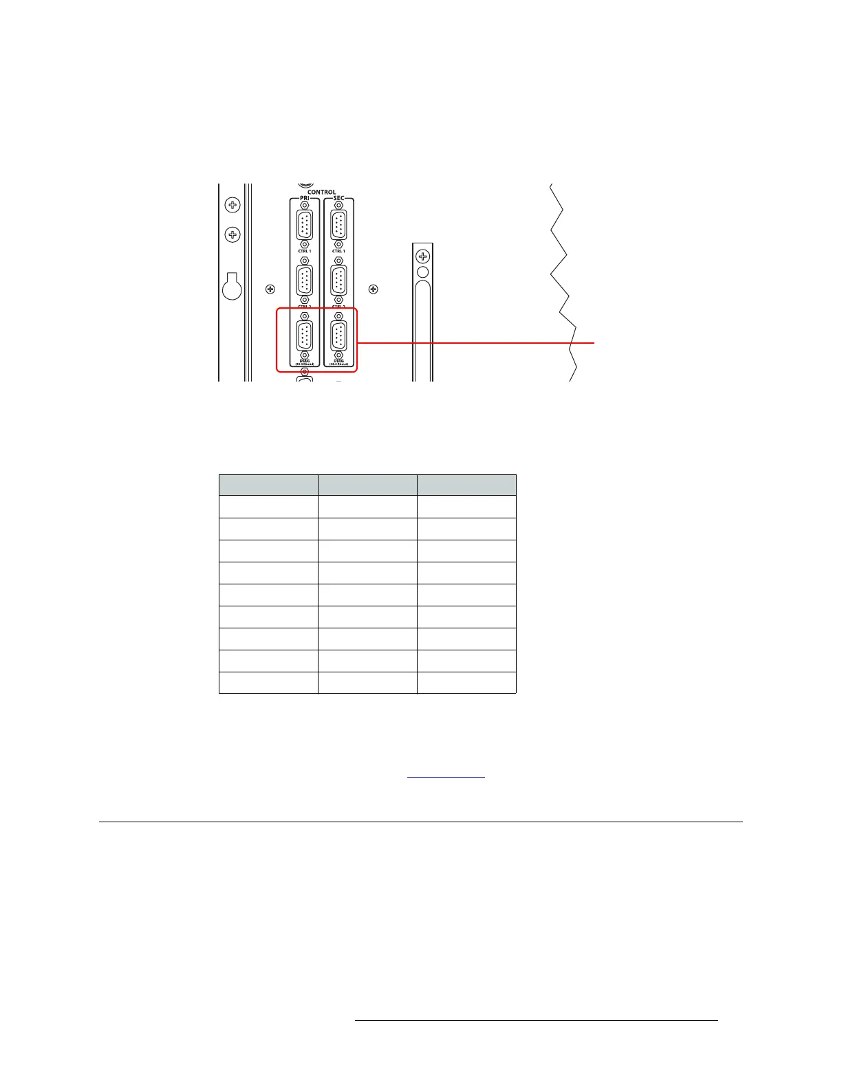
1 Locate the diagnostic connections on the rear of the router, as shown in Figure 2-19. The diag-
nostic connections are labeled ‘DIAG’.
Figure 2-19. Diagnostic Connections (Rear View)
2 Connect to the ‘DIAG’ connection in the ‘PRI’ section using a DE9 connector and a serial
cable. The ports are set for RS-232:
The following lists the DE9 pin connectors for RS-232:
3 Connect the other end of the cable to the PC running the UniConfig application.
4 If a secondary (optional for redundancy) control card is installed, connect to the ‘DIAG’ con-
nection in the ‘SEC’ section using a DE9 connector and a serial cable as described in Step 2 and
Step 3. For more information, see Control Cards
on page 38.
Making AES Reference Connections
The AES reference is used for clock generation and provides a timing reference for AES synchro-
nous signals and for the control card’s timing circuits. For optimum audio output, signals must be
clock-locked to the same reference.
The NV8500 family of routers have as two AES reference connections labeled ‘AES REF 1’ and
‘AES REF 2’. Both connections are used by the primary and the secondary (optional for redun-
dancy) control card. This provides a backup reference source should one of the sources fail. The
Diagnostic Connectors
PC End (DCE) Pins Router End (DTE)
DCD 1 Ground
RXD 2 TXD
TXD 3 RXD
DTR 4 DSR
Signal Ground 5 Signal Ground
DSR 6 DTR
RTS 7 CTS
CTS 8 RTS
Ground 9 Ground
 Loading...