NV8500 family Digital Routers • User’s Guide 35
1. Introduction
Front Module Slots and Rear Connections
secondary (optional for redundancy) control card. For instructions, see Making Diagnostic Connec-
tions on page 74.
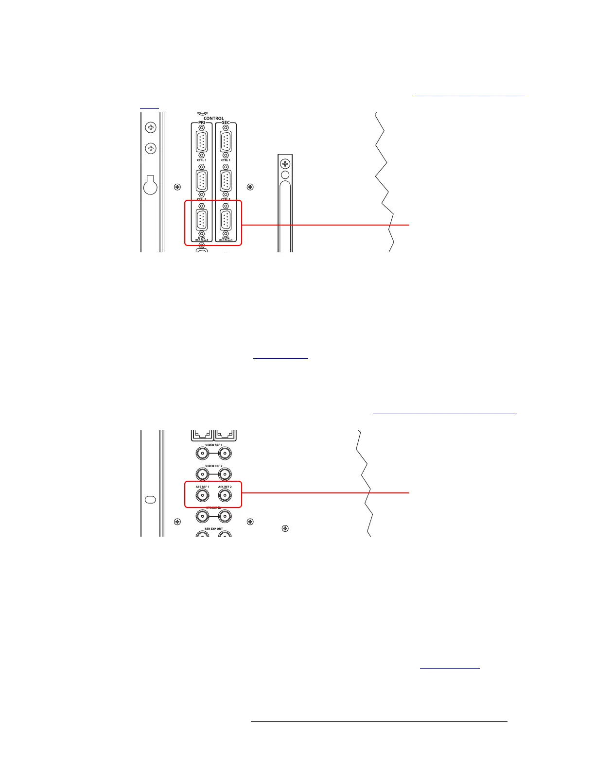
Figure 1-28. Permanent Diagnostic Connections (Rear View)
AES Reference Connections
The AES reference is used for clock generation, which provides a timing reference for AES syn-
chronous signals and for timing circuits on the control card.
Routers in the NV8500 family have two AES reference connections labeled ‘AES REF1’ and ‘AES
REF2’, as shown in Figure 1-29. Both connections are shared by the primary control card and the
secondary control card. (See Control Cards
on page 38.) The AES reference connections are
“redundant” and use the same reference type. When both reference connections are connected, if
one reference fails, the control card automatically fails-over to the redundant reference.
The AES reference connection requires a stable signal source of AES with a sample rate of 48kHz.
For instructions on making AES reference connections, see Making AES Reference Connections
on page 75.
Figure 1-29. Connections to AES References (Rear View)
Video Reference
Routers in the NV8500 family provide timing reference connections for video signals, labeled
‘VIDEO REF 1’ and ‘VIDEO REF 2’, as shown in Figure 1-30. Located on the rear of the router,
these connections provide a reference input for determining the router’s video frame switch point.
The video reference connections require a stable source of PAL, NTSC or Tri-level sync.
If a video reference is present, signals switch at the defined frame and line switch points. If a video
reference is not present, the router still performs the switch, but to an internal reference. If a video
reference is not connected, the control card displays a lit red LED. (See Indicator LEDs
on page
Diagnostic Connectors
AES Reference
Connectors
 Loading...