NV8500 family Digital Routers • User’s Guide 17
1. Introduction
Signal Rates and Flow
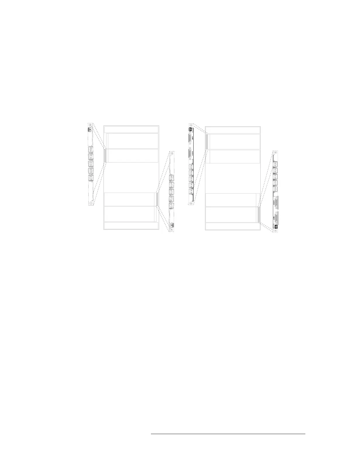
region of the frame the backplanes are rotated 180° from those in the upper portion and “face” in
the opposite direction. Therefore, therefore the top connector is not used.
For signal numbering purposes, the signal numbers in the lower frame start with the second connec-
tor and not the first connector. In other words, in the lower region of the frame, signal numbering
starts with the first usable LC connector.
Figure 1-12 illustrates how signal numbers are applied to LC input backplanes and LC expansion
backplanes in both the upper region and lower region of the router frame.
Figure 1-12. Example of Signal Numbers and LC Backplanes (rear view)
Connectors, Signal Numbers and Specific Frames
The following illustrate how signals are numbered in each NV8500 Family router. When making
physical connections, it is important to review the numbering sequences to ensure the correct signal
number is associated with the correct signal corrector.
For inputs, each card slot manages nine signals. For outputs, each card slot manages 18 signals. For
expansion cards installed in output card slots, each slot manages 9 output signals and two expan-
sion signals.
Inputs
Outputs
Inputs
Outputs
Inputs
Outputs
Inputs
Outputs
Input Backplanes
Expansion Backplanes
1
2
3
4
5
7
8
9
6
Not
used
1
2
3
4
5
7
8
9
6
Not
used
1
2
3
4
5
7
8
9
6
Not
used
1
2
3
4
5
7
8
9
6
Not
used
 Loading...