36 Rev 2.2 • 27 Mar 10
1. Introduction
Front Module Slots and Rear Connections
101.) For instructions on making video reference connections, see Making Video Reference Con-
nections on page 76.
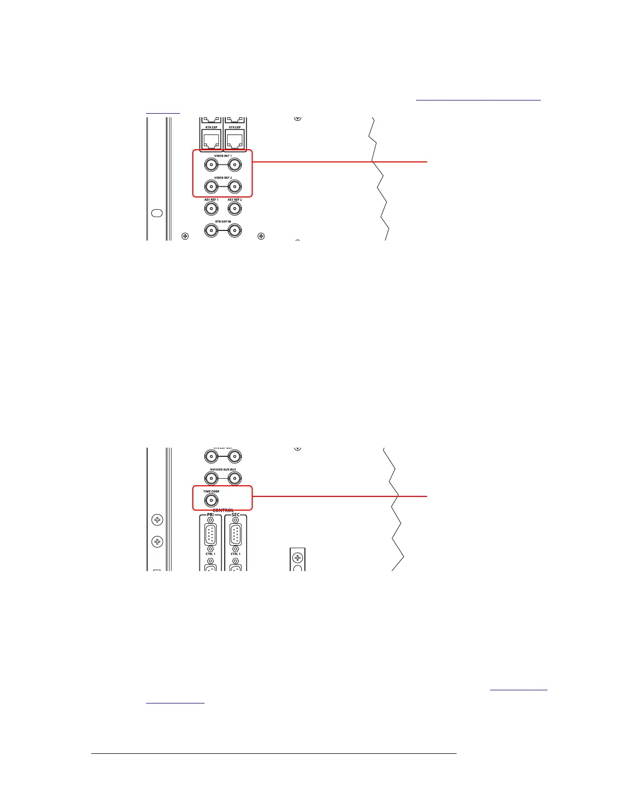
Figure 1-30. Connections to Video References (Rear View)
Redundant and Dual References
There are two video reference connections. The same reference can be used for both connections or
a different reference for each connection. When using the same, or “redundant,” references for both
connections, if one reference fails, the control card fails-over to the redundant reference. When
using different references, or “dual” references, switch takes can occur based on one or the other
reference. For example, if ‘VIDEO REF 1’ uses NTSC as a reference and ‘VIDEO REF 2’ uses
PAL as a reference. Using UniConfig, the type of setting is selected: redundant or dual, and if dual,
which outputs use which video reference on an output by output basis. (See the UniConfig User’s
Guide.)
Time Code Reference Connection
There are two connections for a reference source for Time Code signals labeled ‘TIME CODE’, as
shown in Figure 1-31. However, time code signals are not supported at this time.
Figure 1-31. Time Code Reference Connection (Rear View)
System Alarm
Routers in the NV8500 family have a system alarm that sends notification of a malfunction, such as
when a fan or power supply is not functioning properly. The NV8000 power supply frame (used for
the NV8280/NV8280-Plus and the NV8576/NV8576-Plus) and the routers each have alarm con-
nections that can be connected to external equipment that display visual signals when an alarm is
activated. Creation of an external alarm indicator is outside the scope of this manual, however basic
instructions on wiring the alarm connection for external monitoring is provided. See Alarm Indica-
tor Equipment on page 84.
Video Reference
Connectors
Time Code Connector
 Loading...