82 Rev 2.2 • 27 Mar 10
2. Installation
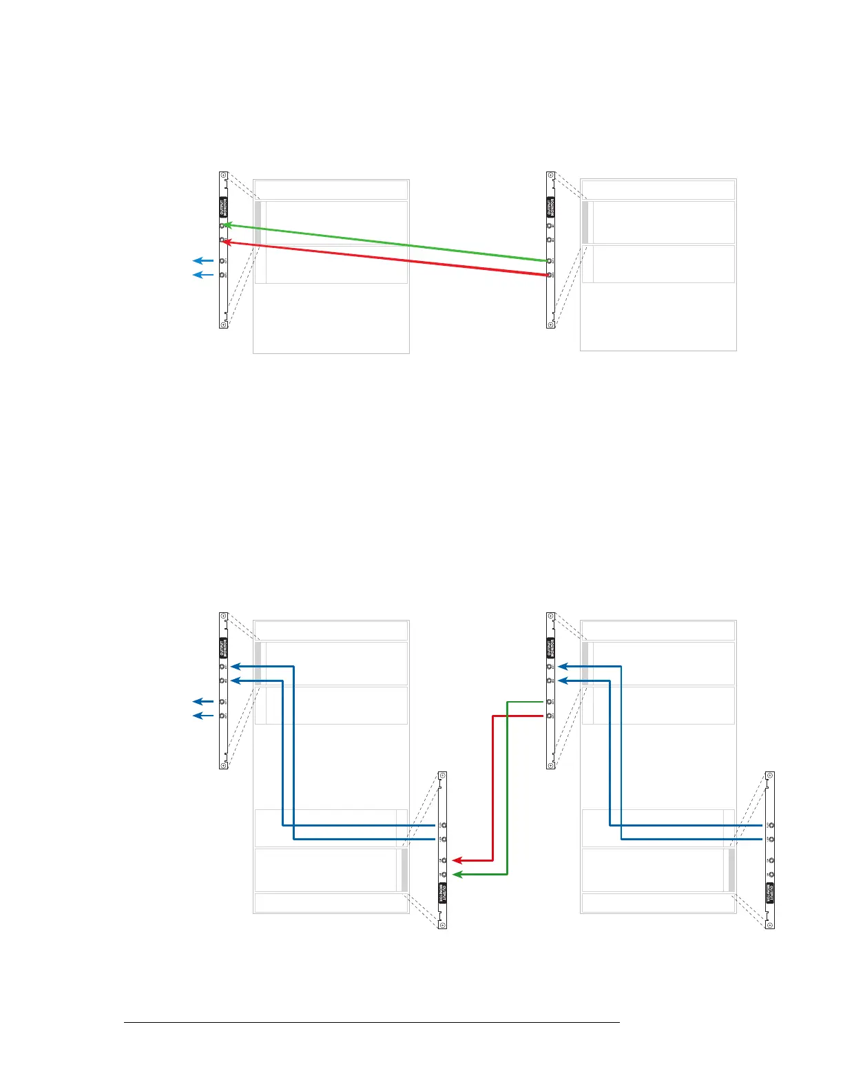
Making Monitor Connections
3 Connect ‘OUT 1’ and ‘OUT 2’ of the output monitor backplane of the primary frame to your
monitoring equipment, as shown in Figure 2-25.
Figure 2-25. NV8576-Plus Connections (Rear View)
How to Make Output Expansion Monitor Connections for NV8576-Plus
1 For each router frame, connect ‘OUT 1’ of the lower output monitor backplane to ‘IN 1’ of the
upper output monitor backplane and ‘OUT 2’ of the lower output monitor backplane to ‘IN 2’
of the upper output monitor backplane, as shown in Figure 2-26.
2 Connect ‘OUT 1’ of the upper output monitor backplane in the secondary frame to ‘IN 1’ of the
lower output monitor backplane of the primary frame, as shown in Figure 2-26.
3 Connect ‘OUT 2’ of the upper output monitor backplane in the secondary frame to ‘IN 2’ of the
lower output monitor backplane of the primary frame, as shown in Figure 2-26.
4 Connect ‘OUT 1’ and ‘OUT 2’ of the upper output monitor backplane of the primary frame to
your monitoring equipment, as shown in Figure 2-26.
Figure 2-26. NV8576-Plus Connections (Rear View)
Inputs
Outputs
Inputs
Outputs
To
equipment
2
Primary Secondary
1
Inputs
Outputs
Inputs
Outputs
Inputs
Outputs
Inputs
Outputs
To
equipment
2
Primary Secondary
1
 Loading...