78 Rev 2.2 • 27 Mar 10
2. Installation
Making Monitor Connections
Monitor Connections
Each monitor backplane has 4 DIN 1.0/2.3 connectors. Using the proprietary cable provided with
the product, connect the monitor backplanes as described for your router and whether in stand-
alone or expanded mode.
Monitor backplanes connectors have unique functions. It is strongly recommended that you review
About Monitor Backplanes
on page 31 before making monitor connections.
How to Make NV8144 Monitor Connections
Because NV8144 only uses one monitor card and backplane, this procedure does not apply to the
NV8280/NV8280-Plus and NV8576/NV8576-Plus routers.
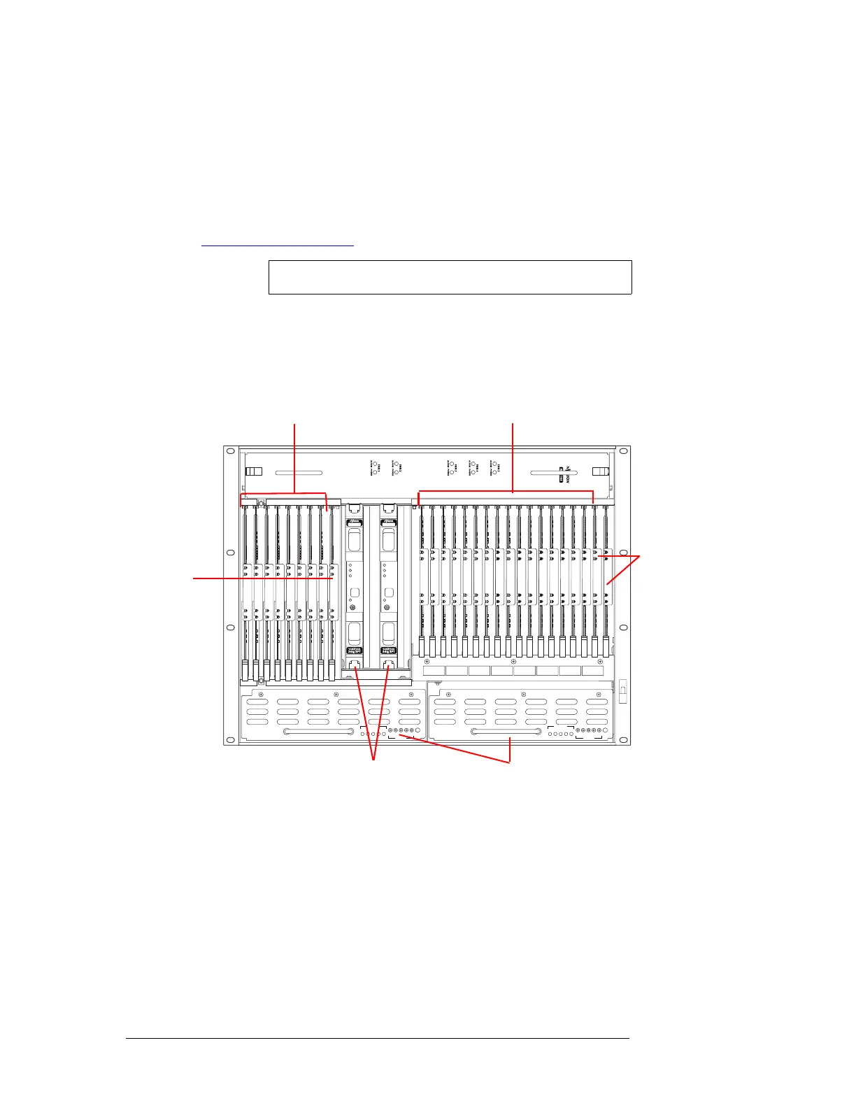
1 Locate the monitor backplane located on the rear of the router frame, as shown in Figure 2-22.
Figure 2-22. NV8144 with Door Removed (Front View)
2 For each connection, use a DIN 1.0/2.3 connector and 1855A Belden cable, or an equivalent
(provided with product package). Connect ‘OUTPUT MON’ and ‘INPUT MON’ on the moni-
tor backplane to your monitoring equipment.
How to Make Output Monitor Connections
Because NV8144 only uses one monitor card and backplane, this procedure does not apply to that
router. This procedure applies to the NV8280/NV8280-Plus and NV8576/NV8576-Plus routers.
Note Unused ‘In’ connectors on the router are not to be terminated.
NV8500 NV8500
PS8100
12345
POWER
GND
12345
48V
+
PS8100
12345
POWER
GND
12345
48V
+
Fan
Output Cards (8)
Monitor
Card
(1)
Input Cards (16)
Control
Cards
(2)
Power Supplies (2)
Crosspoint Cards (2)
 Loading...