NV8500 family Digital Routers • User’s Guide 73
2. Installation
Making Router Control System Connections
How to Make an Ethernet Connection to the Router Control System
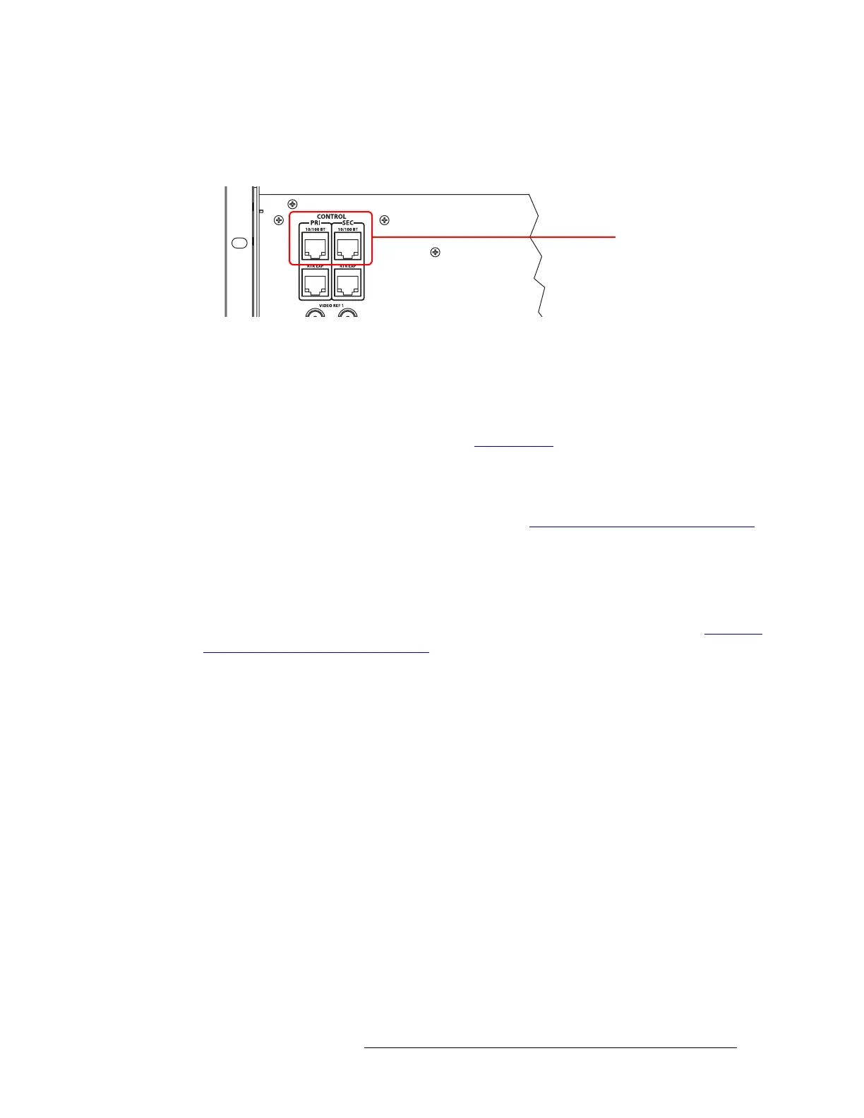
1 Locate the Ethernet connections on the rear of the router, as shown in Figure 2-17. Ethernet
control connections are labeled ‘PRI’ and ‘SEC’.
Figure 2-17. Ethernet Connections to Control System (Rear View)
2 Connect to the ‘10/100 B T’ Ethernet connection in the ‘PRI’ section using a RJ-45 connector
and Cat5, or better, cable.
3 Connect the other end of the cable to an Ethernet hub or switch on the router control system
using a RJ-45 connector.
4 If a secondary (optional for redundancy; see Control Cards
on page 38) control card is installed,
connect to the ‘10/100 B T’ Ethernet connection in the ‘SEC’ section as described in Steps 2
and 3.
5 If two expandable router frames (NV8280-Plus or NV8576-Plus) are being connected together,
make the control system expansion connections. (See Control System Expansion Connections
on page 73.)
Aux Bus Control Connections
The NV8500 family of routers have on Aux Bus connection, labeled ‘AUX BUS’. However, at this
time the connection is not supported. For details, contact Miranda technical support. (See Technical
Support Contact Information on page iii.)
Control System Expansion Connections
Control system expansion connections allow two connected expandable router frames to communi-
cate with the router control system. Only one of the routers is actually connected directly to the
router control system. This router is the primary router. A separate connection is made from the pri-
mary router to the secondary router. This connection allows the router control system to manage
both routers through the connection on the primary router.
The control system expansion port is an RJ-45 port. The connection uses standard Ethernet cable.
Ethernet Connections to
Control System
 Loading...