22 Rev 2.2 • 27 Mar 10
1. Introduction
Front Module Slots and Rear Connections
Below the input card slots, at the bottom of the frame, are 10 crosspoint card slots. The fifth and
sixth crosspoint card slots house an optional redundant crosspoint cardset (two-card module).
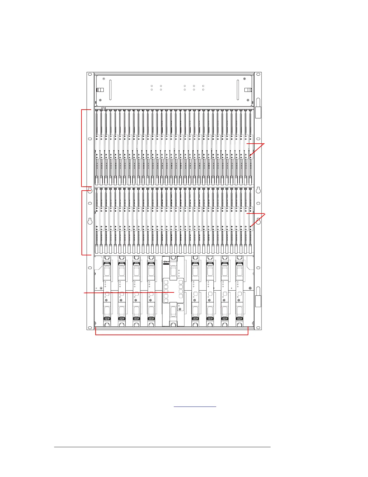
Figure 1-17. NV8280/NV8280-Plus with Door Removed (Front View)
NV8576 and NV8576-Plus
Figure 1-18 shows the front of the NV8576 router frame with the door removed. From this view,
you can see the modules inserted in the slots. The NV8576 and the NV8576-Plus have identical
frames. Unique expansion output cards and corresponding expansion output backplanes enable the
NV8576-Plus router to connect to another NV8576-Plus frame. The frames themselves are not
changed. For more information, see Frame Expansion
on page 45.
The router is divided into three general regions: upper, middle and lower. The upper and lower
regions are mirror images of each other featuring 32 slots for output cards and 32 slots for input
NV8280
144 X 144
3Gig
Redundant
XPT
STANDBY
PATH
LITE
ALARM
ACTIVE
POWER
REDUNDANT OPERAT ION
1
7
2
8
3
9
4
10
NV8500 NV8500NV8500 NV8500 NV8500 NV8500 NV8500 NV8500 NV8500
Fan
Monitor
Cards
(2)
Input
Control
Cards
(2)
Crosspoint Cards (8)
Cards
(32)
Output
Cards
(32)
Redundant
Crosspoint
Cardset (1)
 Loading...