10 Rev 2.2 • 27 Mar 10
1. Introduction
Signal Rates and Flow
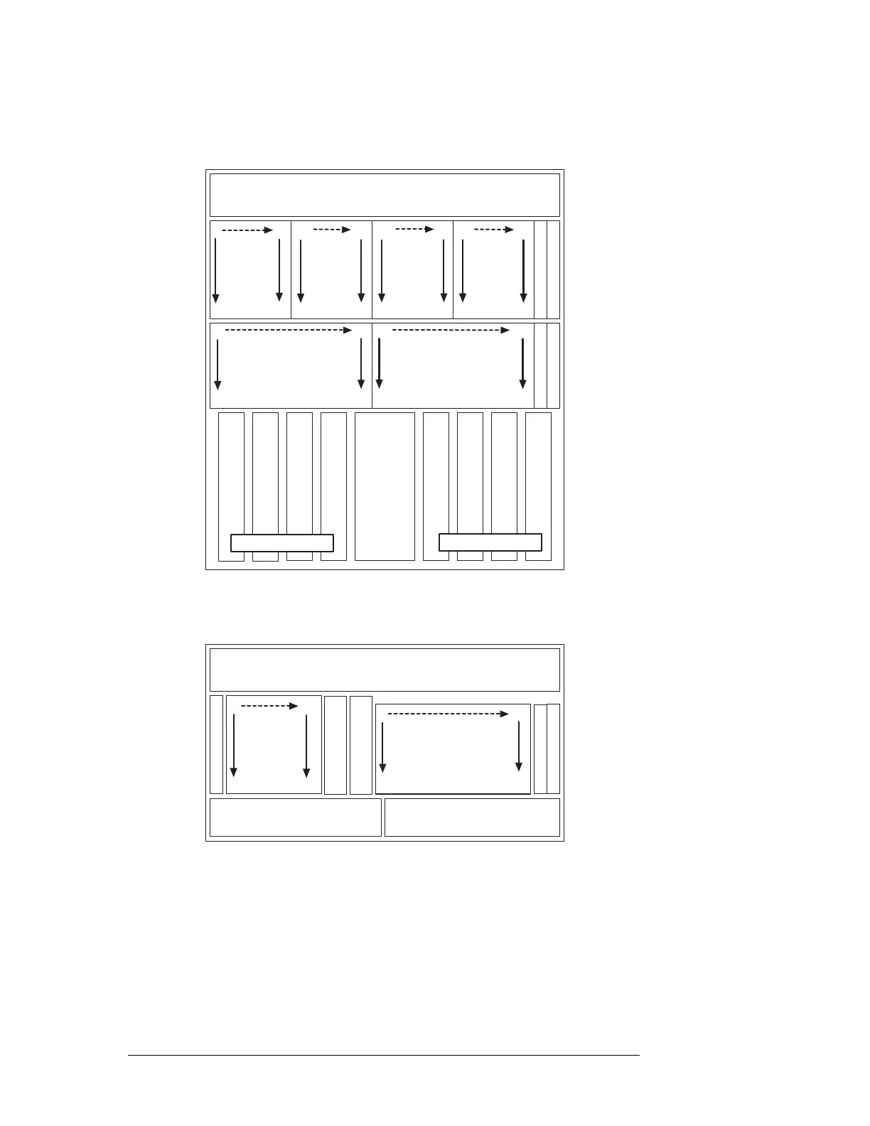
Figure 1-8 shows the standalone NV8280 frame and which signal numbers correspond to which
slots when viewing the router from the front.
Figure 1-6. Example of NV8280 Slots and Corresponding Signal Numbers (Front View)
Figure 1-7 shows the standalone NV8144 frame and which signal numbers correspond to which
slots when viewing the router from the front.
Figure 1-7. Example of NV8144 Slots and Corresponding Signal Numbers (Front View)
Expandable Frames and Signal Numbers
Expandable router frames contain backplanes similar to the standalone routers except that the con-
nectors housed on the backplanes are different. Each backplane contains either 9 input connectors
or 9 output connectors plus two high-density expansion connectors. This means that input slot 1
corresponds to inputs 1–9, input slot 2 corresponds to inputs 10–18, and so on, up to the maximum.
For outputs, output slot 1 corresponds to local outputs 1–9 and forwards through the expansion
connectors outputs to the second router, and so on. For example, in the NV8576-Plus frame, output
FAN
INPUTS
1144
XPT (INPUTS 1144)
INPUT MONITOR
(8 cards)
OUTPUTS
145288
(8 cards)
OUTPUTS
289432
(8 cards)
OUTPUTS
433576
(8 cards)
OUTPUT MONITOR
(16 cards)
INPUTS
145288
(16 cards)
OUTPUTS 1288
OUTPUTS 289576
SEC. CONTROL
PRIM. CONTROL
XPT (INPUTS 1144)
XPT (INPUTS 145288)
XPT (INPUTS 145288)
XPT (INPUTS 1144)
XPT (INPUTS 1144)
XPT (INPUTS 145288)
XPT (INPUTS 145288)
REDUNDANT CROSSPOINT
OUTPUTS
1144
1
18
127
144
145
288162
271
289
306
432
415
433
576
450
559
145
153
288
280
1
9
136
144
FAN
INPUTS
1144
MONITOR
(16 cards)
SEC. CONTROL
PRIM. CONTROL
(8 cards)
XPT (INPUTS 1144)
XPT (INPUTS 1144)
POWER SUPPLY
POWER SUPPLY
1
9
136
144
OUTPUTS
1144
1
18
127
144
 Loading...